Archive for the ‘Graphics and Rendering’ Category

Using feColorMatrix to dynamically recolor icons (part 2, two-color icons)

Previously, I looked at how to use feColorMatrix to dynamically change the color of single-color icons. In this post, we’ll look at using feColorMatrix, feBlend, and feComposite to implement an algorithm that allow for dynamically changing the the colors of an icon with 2 colors.

The Algorithm

With a single color, we could think of the process as being a single step: applying the color transformation matrix with the desired R, G, B values. For two colors, there are multiple steps and matrices involved, so it’s worth having a high-level overview and conceptual understanding of the algorithm before delving into the details.

  • The input icon will have 2 color, black and white; black areas will be changed to colorA and white areas will be changed to colorB
  • Add colorA to the source image (black areas will take on the new color, white areas will remain white), the result is imageA
  • Invert the source image, then add colorB to it (black areas will become white and remain white, white areas will become black and take on the new color), the result is imageB
  • Combine imageA and imageB, such that the alpha component from the source image is preserved, output the result
Dynamically recolor two-color icon

Note that from the above, we see the key operations that are needed:

  • Add
  • Invert
  • Combine

Another look at the color transformation matrix for applying a single-color

Note that the transformation matrix used previously for the single-color case, only preserves the alpha component from the input. The R, G, and B components are thrown away:

[[0, 0, 0, 0, R], [0, 0, 0, 0, G], [0, 0, 0, 0, B], [0, 0, 0, 1, 0]][(R_(src)), (G_(src)), (B_(src)), (A_(src))] = [(R), (G), (B), (A_(src))]

It doesn’t matter what color the input pixel is, applying the transformation matrix will result in those Rsrc Gsrc Bsrc input values being multiplied by zero, before the new/output R, G, B values are added in.

While this is fine for the single-color case, for the two-color algorithm to work, the distinction between the black areas and the white areas need to be kept intact, so we have to work with the Rsrc Gsrc Bsrc values from the input vector and preserve the distinction.

Making Rsrc Gsrc Bsrc part of the transformation

Modifying the transformation matrix to allow Rsrc Gsrc Bsrc to be part of the calculations requires the first 3 diagonal elements of the matrix to be non-zero.

The simplest case of this is the identity matrix:

[[1, 0, 0, 0, 0], [0, 1, 0, 0, 0], [0, 0, 1, 0, 0], [0, 0, 0, 1, 0]][(R_(src)), (G_(src)), (B_(src)), (A_(src))] = [(R_(src)), (G_(src)), (B_(src)), (A_(src))]

Let’s look at a few matrices that define transformations needed for the algorithm.

The add colorK matrix:

[[1, 0, 0, 0, R_(k)], [0, 1, 0, 0, G_(k)], [0, 0, 1, 0, B_(k)], [0, 0, 0, 1, 0]][(R_(src)), (G_(src)), (B_(src)), (A_(src))] = [(R_(src) + R_(k)), (G_(src) + G_(k)), (B_(src) + B_(k)), (A_(src))]

The invert matrix:

[[-1, 0, 0, 0, 1], [0, -1, 0, 0, 1], [0, 0, -1, 0, 1], [0, 0, 0, 1, 0]][(R_(src)), (G_(src)), (B_(src)), (A_(src))] = [(-R_(src) + 1), (-G_(src) + 1), (-B_(src) + 1), (A_(src))]

The above can be combined into a single transformation matrix, the invert & add colorK matrix:

[[-1, 0, 0, 0, 1 + R_(k)], [0, -1, 0, 0, 1 + G_(k)], [0, 0, -1, 0, 1 + B_(k)], [0, 0, 0, 1, 0]][(R_(src)), (G_(src)), (B_(src)), (A_(src))] = [(-R_(src) + 1 + R_(k)), (-G_(src) + 1 + G_(k)), (-B_(src) + 1 + B_(k)), (A_(src))]

Putting aside and referencing intermediate results

Note that the algorithm requires us to create 2 independent images (imageA and imageB) and then subsequently combine them.

This can be accomplished by utilizing the result attribute available on SVG filter primitive elements. By specifying a result identifier we are able to apply a transformation and put aside the resultant image.

Combining the intermediate results

Combining intermediate results/images can’t be done with feColorMatrix, it’s simply not an operation that can be constructed as a transformation. To handle this, SVG provides the feBlend element with a number of predefined operations available via the mode attribute. Based on the color transformations done to create imageA and imageB (mainly that the areas that are not of concern, the background, are set to white [1,1,1]), the multiply operation will work to combine the images (not perfectly, there’s one big problem with the alpha channel, but we’ll deal with that in a bit).

image multiply
<feBlend 
    color-interpolation-filters="linearRGB"
    in="imageA" 
    in2="imageB" 
    mode="multiply" 
    result="output" />        

The alpha channel problem

While feBlend seem to accomplish what’s needed, for anything other than a white background you’ll notice a white-ist outline around elements in the image, as you can see below.

alpha channel problems with feBlend

The problem is that for what we’re trying to accomplish we just want to simply preserve the alpha channel, not blend it in any way. However, all feBlend operations will perform a blend of the alpha channel. From the SVG spec:

image multiply

So there’s no way we can really work with feBlend to get a solution for the alpha channel, but we do have an idea of what the solution is: copy the alpha channel from the source image.

Fixing the alpha channel

Fixing the alpha channel will involve 2 steps:

  • For the image outputted by feBlend, get the alpha value to be 1 for every pixel
    (the reason this step will become apparent once we look at how feComposite has to be used)
  • Use feComposite to construct an image with the alpha values from the source image and the R,G,B values from the image outputted by feBlend

The first step is simple. We just need a slight modification to the 2 color transformation matrices used, such that one or both set the alpha channel to 1 for every pixel (note from the alpha blending equation, this will effectively set the alpha value to 1 for every pixel in the output). The modified matrices are shown below and it’s a good point to start showing some code.

The full-alpha add colorK matrix:

[[1, 0, 0, 0, R_(k)], [0, 1, 0, 0, G_(k)], [0, 0, 1, 0, B_(k)], [0, 0, 0, 0, 1]][(R_(src)), (G_(src)), (B_(src)), (A_(src))] = [(R_(src) + R_(k)), (G_(src) + G_(k)), (B_(src) + B_(k)), (1) ]

<feColorMatrix in="SourceGraphic" type="matrix" result="imageA"
    values="1 0 0 0 0
            0 1 0 0 0.68235294117
            0 0 1 0 0.93725490196
            0 0 0 0 1" /> 

The full-alpha invert & add colorK matrix:

[[-1, 0, 0, 0, 1 + R_(k)], [0, -1, 0, 0, 1 + G_(k)], [0, 0, -1, 0, 1 + B_(k)], [0, 0, 0, 0, 1]][(R_(src)), (G_(src)), (B_(src)), (A_(src))] = [(-R_(src) + 1 + R_(k)), (-G_(src) + 1 + G_(k)), (-B_(src) + 1 + B_(k)), (1)]

<feColorMatrix in="SourceGraphic" type="matrix" result="imageA"
    values="-1 0 0 0 1.0784313725
            0 -1 0 0 1.7058823529
            0 0 -1 0 1.2431372549
            0 0 0 0 1" />

For the next and final step, we need to take a look at feComposite.

The feComposite filter primitive allows for more fine-grained operations on pixels using the supported “arithmetic” operation:

feComposite arithmetic operation

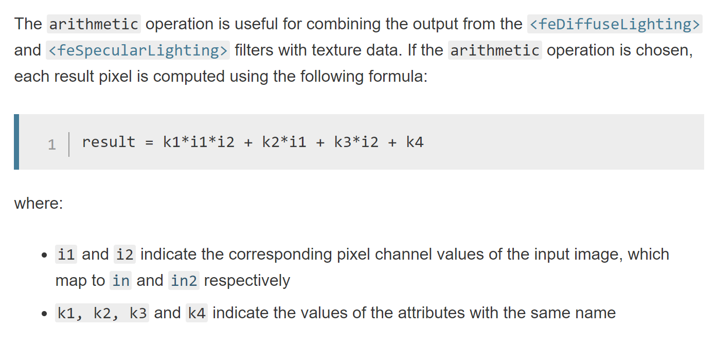
As this operation is done on every channel, including the alpha channel, we have way to control what happens to the alpha pixels in a composition of 2 images.

We’re going to make use of this by:

  • Using an feColorMatrix, where the input in the source image, and transforming such that R,G,B is white [1,1,1] and the alpha remains unchanged
  • Using feComposite to do a simple arithmetic multiply (k1=1, k2=0, k3=0, k4=0), between the image constructed above (where R,G,B is [1,1,1] and alpha is the alpha from the source image) and the output from feBlend (where the R,G,B = the values we want for the output and alpha = 1)

Effectively, the source alpha is multiplied by 1 (as the image produced from the feBlend operation has the alpha set to 1 for all pixels) and the R,G,B values from the feBlend output are multiplied by 1 (as the constructed image, in the first step above, sets R,G,B to 1 for every pixel).

<!-- Get and use alpha from source image -->
<feColorMatrix in="SourceGraphic" type="matrix" result="whiteAlpha"
    values="0 0 0 0 1
            0 0 0 0 1
            0 0 0 0 1
            0 0 0 1 0" />     

<feComposite in="whiteAlpha" in2="outputFullAlpha" operator="arithmetic" k1="1" k2="0" k3="0" k4="0" />

Pulling everything together

We now have all the pieces for the filter and here’s what the code looks like:

<svg style="width:0; height:0; margin:0; padding:0; border:none;">
    <filter color-interpolation-filters="sRGB" id="colorTransformFilter">

        <feColorMatrix in="SourceGraphic" type="matrix" result="imageA"
            values="1 0 0 0 0
                    0 1 0 0 0.68235294117
                    0 0 1 0 0.93725490196
                    0 0 0 0 1" /> 

        <feColorMatrix in="SourceGraphic" type="matrix" result="imageB"
            values="-1 0 0 0 1.0784313725
                    0 -1 0 0 1.7058823529
                    0 0 -1 0 1.2431372549
                    0 0 0 0 1" />              
                    
        <feBlend 
            color-interpolation-filters="linearRGB"
            in="imageA" 
            in2="imageB" 
            mode="multiply" 
            result="outputFullAlpha" />        

        <!-- Get and use alpha from source image -->
        <feColorMatrix in="SourceGraphic" type="matrix" result="whiteAlpha"
            values="0 0 0 0 1
                    0 0 0 0 1
                    0 0 0 0 1
                    0 0 0 1 0" />     

        <feComposite in="whiteAlpha" in2="outputFullAlpha" operator="arithmetic" k1="1" k2="0" k3="0" k4="0" />

    </filter>
</svg>

The demo below uses the filter, along with a bit of Javascript to cycle and update the input colors (i.e. dynamically updating the values plugged into the first 2 feColorMatrix elements):

Limitations

We have the same limitations I mentioned in part 1:

  • For icons applied as background-images, the CSS filter property isn’t ideal. CSS filter will effect not only the element it’s applied to, but all child elements as well
  • As is the case with mixing the CSS filter property and the SVG filter element, effects governed by the CSS transition property won’t work

In addition, because of how the alpha channel in treated in regards to feBlend (setting all pixels to have alpha=1), you more than likely won’t get good results if the icon has different-colored adjoining or overlapping elements, as you won’t get a smooth transition at the edges/boundaries.

Using feColorMatrix to dynamically recolor icons (part 1, single-color icons)

I’ve been experimenting with using feColorMatrix as an elegant way to dynamically color/re-color SVG icons. Here I’ll look at working with single-color icons.

Working directly with the SVG markup

Changing the stroke and/or fill colors of the SVG elements directly can be a good solution in many cases, but it requires:

  • Placing the SVG markup into the document to query and modify the appropriate elements when a color update is needed (note that this option isn’t viable if you need to place the icon in an <img> tag or it needs to be placed as a background-image on an element, as you can’t reference the SVG element in such cases)
  • Treating the SVG markup as a templated, Javascript, string to make a data-URI, and re-making it when a color update is needed

By using the color transformation matrix provided by feColorMatrix these restrictions go away and we also get back the flexibility of using external files.

Icon color

Keep in mind, we’re only dealing with single-color icons. What color is used doesn’t technically matter, but black is a nice basis and in an actual project, black is beneficial, as you’re able to open your the icon files in an editor or browser and actually see it.

black colored icon

A black pixel within the icon can then be represented by the following vector:

black pixel as column vector

Note that the alpha component may vary due to antialiasing (to smooth out edges) or some translucency within the icon.

The color transformation matrix

feColorMatrix allows you to define a 5×4 transformation matrix. There’s a lot you can do with that, but note that the last column of the matrix is essentially an additive component for each channel (see matrix-vector multiplication), so in that column we enter the desired R, G, B values from top to bottom, which will be added to the zeros in the input vector. Next, we want to preserve the alpha component from the input vector, so the fourth column of the matrix becomes [0, 0, 0, 1]T and the fourth row of the last column is zero, as we don’t want to add anything to the alpha component.

color transformation matrix, [[0, 0, 0, 0, R], [0, 0, 0, 0, G], [0, 0, 0, 0, B], [0, 0, 0, 1, 0]][(0), (0), (0), (A_(src))] = [(R), (G), (B), (A_(src))]

The matrix-vector multiplication gives a new vector (that defines the output pixel) with the entered R, G, B values and the alpha value from the source pixel.

Representing the matrix within an feColorMatrix element is straightforward…

<feColorMatrix in="SourceGraphic" type="matrix"
values="0 0 0 0 R
0 0 0 0 G
0 0 0 0 B
0 0 0 1 0"
/>

… just plug in values for R, G, B.

Applying the color transformation

The color transformation matrix can be applied to an element by wrapping it in an SVG filter element and referencing the filter via the CSS filter property.

With Javascript, the values attribute of the feColorMatrix element can be updated dynamically. The color change will, in turn, be reflected in any elements referencing the SVG filter.

<!DOCTYPE html>
<html>
<body>
<!--
The values of the color matrix defines the color transformation what will be applied.
Here we just setup the elements and define an identity matrix. We'll modify the matrix via Javascript code
to define an actual color transformation.
-->
<svg style="width:0; height:0; margin:0; padding:0; border:none;">
<filter
color-interpolation-filters="sRGB" id="colorTransformFilter">
<feColorMatrix
in="SourceGraphic" type="matrix"
values="1 0 0 0 0
0 1 0 0 0
0 0 1 0 0
0 0 0 1 0"
/>

</filter>
</svg>

<!--
Element with an SVG icon that we want to colorize
Note: that the color transformation is applied to everything not only to the background, but everything
within the element as well.

Typical solution to to isolate background stuff to it's own div and use another div for contents

-->
<div id="logo-colored"
style="
width:300px;
height:300px;
background-color: transparent;
background-image: url(logo.svg);
background-position: center center;
background-repeat: no-repeat;
background-size: cover;
filter:url(#colorTransformFilter);"
>

<p
style="color:#fff">Testing 1 2 3...</p>
</div>

<script
type="text/javascript">
/**
* A little helper function to update the color transformation matrix
*
* @param {Number} _r
* @param {Number} _g
* @param {Number} _b
*/
const setPrimaryColor = function(_r, _g, _b) {

const rScaled = _r / 255.0;
const gScaled = _g / 255.0;
const bScaled = _b / 255.0;

const feColorMatrixElem = document.getElementById('colorTransformFilter').getElementsByTagName('feColorMatrix')[0];
feColorMatrixElem.setAttribute(
`values`,
`0 0 0 0 ${rScaled}
0 0 0 0 ${gScaled}
0 0 0 0 ${bScaled}
0 0 0 1 0`
);
};

// Set/update color transformation matrix
setPrimaryColor(129, 0, 0);
</script>

</body>
</html>

The code will take a black-colored icon and re-color it to [129, 0, 0], as seen below:

Limitations

This technique provides a lot of flexibility, but it’s not without it’s limits.

  • For icons applied as background-images, the CSS filter property isn’t ideal. CSS filter will effect not only the element it’s applied to, but all child elements as well. Note the “Testing 1 2 3…” paragraph is re-colored in the demo above.
  • As is the case with mixing the CSS filter property and the SVG filter element, effects governed by the CSS transition property won’t work.

Similar techniques

  • For shifting between colors, the hue-rotate() CSS filter function can be a solution. However, in practice, I don’t find this intuitive and color changes are rarely just hue rotations.
  • A more limited case, transitioning a colored icon to white, can be achieved with 2 CSS filter functions, brightness(0) and invert(100%).
  • You can do crazier things by trying to compute and fit a solution to the hue-rotation, saturation, sepia, and invert filter functions; however this is both complex to grasp and produces inexact/approximate color matches.
  • An SVG filter using feComponentTransfer should work, but I don’t find it as intuitive to work with.

Resources

If you want to interactively play around with feColorMatrix, check out SVG Color Filter Playground.

Brute-force convex hull construction

I’ve been experimenting a bit with convex hull constructions and below I’ll explain how to do a brute-force construction of a hull.

It’s worth noting up-front that the brute-force method is slow, O(n3) worst case complexity. So why bother? I think there are a few compelling reasons:

  • The brute-force method expresses the fundamental solution, which gives you the basic building blocks and understanding to approach more complex solutions
  • It’s faster to implement
  • It’s still a viable solution when n is small, and n is usually small.

What is a convex hull?

You can find a formal definition on Wikipedia. Informally, and specific to computational geometry, the convex hull is a convex polygon in which all points are either vertices of said polygon or enclosed within the polygon.

Brute-force construction

  • Iterate over every pair of points (p,q)
  • If all the other points are to the right (or left, depending on implementation) of the line formed by (p,q), the segment (p,q) is part of our result set (i.e. it’s part of the convex hull)

Here’s the top-level code that handles the iteration and construction of resulting line segments:

/**
* Compute convex hull
*/
var computeConvexHull = function() {
console.log(
"--- ");

for(var i=0; i<points.length; i++) {
for(var j=0; j<points.length; j++) {
if(i === j) {
continue;
}

var ptI = points[i];
var ptJ = points[j];

// Do all other points lie within the half-plane to the right
var allPointsOnTheRight = true;
for(var k=0; k<points.length; k++) {
if(k === i || k === j) {
continue;
}

var d = whichSideOfLine(ptI, ptJ, points[k]);
if(d < 0) {
allPointsOnTheRight =
false;
break;
}
}

if(allPointsOnTheRight) {
console.log(
"segment " + i + " to " + j);
var pointAScreen = cartToScreen(ptI, getDocumentWidth(), getDocumentHeight());
var pointBScreen = cartToScreen(ptJ, getDocumentWidth(), getDocumentHeight());
drawLineSegment(pointAScreen, pointBScreen);
}

}
}
};

The “secret sauce” is the whichSideOfLine() method:

/**
* Determine which side of a line a given point is on
*/
var whichSideOfLine = function(lineEndptA, lineEndptB, ptSubject) {
return (ptSubject.x - lineEndptA.x) * (lineEndptB.y - lineEndptA.y) - (ptSubject.y - lineEndptA.y) * (lineEndptB.x - lineEndptA.x);
};

This is a bit of linear algebra derived from the general equation for a line.

The result represents the side of a line a point is one, based on the sign of the result. We can check if the point is on the left or on the right, it doesn’t matter as long as there is consistency and the same check is done for all points.

How it looks

I made a few diagrams to show the first few steps in the algorithm, as segments constituting the convex hull are found. The shaded area represents our success case, where all other points are to the right of the line formed by the points under consideration. Not shown are the failure cases (i.e. one or more points are on the left of the line formed by the points under consideration).

convex hull construction, brute force, step 1

convex hull construction, brute force, step 1

convex hull construction, brute force, step 1

Code and Demo

You can play around with constructing a hull below by double-clicking to add vertices.

You can find the code on GitHub.

Post-process shaders in glfx

Pushed an update to glfx to allow for post-process shading. When a post-process shader is defined, the scene is rendered to a screen-space quad (the size of the viewport), and that quad is then rendered to the viewport with the post-process shader applied.

The shader is loaded (asynchronously) like any other:

glfx.shaders.load('screenspace.fs', "frag-shader-screenspace", glfx.gl.FRAGMENT_SHADER);

Once loaded, we create the shader program, and get locations for whatever variables are used. The vertex shader isn’t anything special, it just transforms a vertex by the model-view and projection matrices, and passes along the texture coordinates.

glfx.whenAssetsLoaded(function() {

var postProcessShaderProgram = glfx.shaders.createProgram([glfx.shaders.buffer['vert-shader-basic'], glfx.shaders.buffer['frag-shader-screenspace']],
function(_shprog) {

// Setup variables for shader program
_shprog.vertexPositionAttribute = glfx.gl.getAttribLocation(_shprog, "aVertexPosition");
_shprog.pMatrixUniform = glfx.gl.getUniformLocation(_shprog,
"uPMatrix");
_shprog.mvMatrixUniform = glfx.gl.getUniformLocation(_shprog,
"uMVMatrix");
_shprog.textureCoordAttribute = glfx.gl.getAttribLocation(_shprog,
"aTextureCoord");

_shprog.uPeriod = glfx.gl.getUniformLocation(_shprog,
"uPeriod");
_shprog.uSceneWidth = glfx.gl.getUniformLocation(_shprog,
"uSceneWidth");
_shprog.uSceneHeight = glfx.gl.getUniformLocation(_shprog,
"uSceneHeight");

glfx.gl.enableVertexAttribArray(_shprog.vertexPositionAttribute);
glfx.gl.enableVertexAttribArray(_shprog.textureCoordAttribute);

});

...

We then tell glfx to apply our post-process shader program:

glfx.scene.setPostProcessShaderProgram(postProcessShaderProgram);

This call will result in different rendering path, which renders the scene to a texture, applies that texture to a screen-space quad, and renders the quad with the post-process shader.

Here is the shader for screenspace.fs, used in the demo shown above:

precision mediump float;

uniform float uPeriod;
uniform float uSceneWidth;
uniform float uSceneHeight;
uniform sampler2D uSampler;        
varying vec2 vTextureCoord;

void main(void) {

vec4 sum = vec4( 0. );
float blurSampleOffsetScale = 2.8;
float px = (1.0 / uSceneWidth) * blurSampleOffsetScale;
float py = (1.0 / uSceneHeight) * blurSampleOffsetScale;

vec4 src = texture2D( uSampler, ( vTextureCoord ) );

sum += texture2D( uSampler, ( vTextureCoord + vec2(-px, 0) ) );
sum += texture2D( uSampler, ( vTextureCoord + vec2(-px, -py) ) );
sum += texture2D( uSampler, ( vTextureCoord + vec2(0, -py) ) );
sum += texture2D( uSampler, ( vTextureCoord + vec2(px, -py) ) );
sum += texture2D( uSampler, ( vTextureCoord + vec2(px, 0) ) );
sum += texture2D( uSampler, ( vTextureCoord + vec2(px, py) ) );
sum += texture2D( uSampler, ( vTextureCoord + vec2(0, py) ) );
sum += texture2D( uSampler, ( vTextureCoord + vec2(-px, py) ) );
sum += src;

sum = sum / 9.0;

gl_FragColor = src + (sum * 2.5 * uPeriod);

}

Note that it requires a few uniforms to be supplied to it, we use the glfx.scene.onPostProcessPreDraw() callback to setup the variables (before the post-processed scene is drawn):

var timeAcc = 0;
glfx.scene.onPostProcessPreDraw =
function(tdelta) {

timeAcc += tdelta;
var timeScaled = timeAcc * 0.00107;

if(timeScaled > 2.0*Math.PI) {
timeScaled = 0;
timeAcc = 0;
}

var period = Math.cos(timeScaled);
glfx.gl.uniform1f(postProcessShaderProgram.uPeriod, period + 1.0);

glfx.gl.uniform1f(postProcessShaderProgram.uSceneWidth, glfx.gl.viewportWidth);
glfx.gl.uniform1f(postProcessShaderProgram.uSceneHeight, glfx.gl.viewportHeight);
};

What we’re doing is using the scene rendering time deltas to generate a periodic/sinusoidal wave. This results in the pulsing brightness/fading effect of the scene. The brightness effect itself is done by adding the source pixel to a blurred + brightened version of itself. The blurring allows for the soft fade in and fade out.

GLSL variable qualifiers

I’ve been playing around with WebGL shader code recently and found this bit on variable prefixes helpful, particularly in the explanation of the variable qualifiers:

  • Attribute: data provided by buffers
  • Uniform: inputs to the shaders
  • Varying: values passed from a vertex shader to a fragment shader and interpolated (or varied) between the vertices for each pixel drawn

Something important to keep in mind is that this relates to the OpenGL ES Shading Language, Version 1.00, which is (unfortunately) what’s currently supported by WebGL.

A WebGL implementation must only accept shaders which conform to The OpenGL ES Shading Language, Version 1.00 [GLES20GLSL], and which do not exceed the minimum functionality mandated in Sections 4 and 5 of Appendix A.

Attribute and Varying were part of early versions of, OpenGL-supported, GLSL, but are deprecated as of OpenGL 3.0 / GLSL 1.30.10, and replaced with more generic constructs:

  • in is for input from the previous pipeline stage, i.e. per vertex (or per fragment) values at most, per primitive if using glAttribDivisor and hardware instanciation
  • out is for output to the next stage

Real-time image processing on the web

A while ago I began playing around with grabbing a video stream from a webcam and seeing what I could do with the captured data. Capturing the video stream using the navigator.getUserMedia() navigator.mediaDevices.getUserMedia() method was straightforward, but directly reading and writing the image data of the video stream isn’t possible. That said, the stream data can be put onto a canvas using CanvasRenderingContext2D.drawImage(), giving you the ability to manipulate the pixel data.

const videoElem = document.querySelector('video'); // Request video stream navigator.mediaDevices.getUserMedia({video: true, audio: false}) .then(function(_videoStream) { // Render video stream on <video> element videoElem.srcObject =_videoStream; }) .catch(function(err) { console.log(`getUserMedia error: ${err}`); } ); const videoElem = document.querySelector('video'); const canvas = document.querySelector('canvas'); const ctx = canvas.getContext('2d'); // put snapshot from video stream into canvas ctx.drawImage(videoElem, 0, 0);

You can read and write to the <canvas> element, so hiding the <video> element with the source data and just showing the <canvas> element seems logical, but the CanvasRenderingContext2D.drawImage() call is expensive; looking at the copied stream on the <canvas> element there is, very noticeable, visual lag. Another reason to avoid this option is that the frequency at which you render (e.g. 30 FPS), isn’t necessarily the frequency at which you’d want to grab and process image data (e.g. 10 FPS). The disassociation allows you to keep the video playback smooth, for a better user experience, but more effectively utilize CPU cycles for image processing. At least in my experience so far, a small delay in visual feedback from image processing is acceptable and looks perfectly fine intermixed with the higher-frequency video stream.

So the best options all seem to involve showing the <video> element with the webcam stream and placing visual feedback on top of the video in some way. A few ideas:

  • Write pixel data to another canvas and render it on top of the <video> element
  • Render SVG elements on top of the <video> element
  • Render DOM elements (absolutely positioned) on top of the <video> element

The third option is an ugly solution, but it’s fast to code and thus allows for quick prototyping. The demo and code below shows a quick demo I slapped together using <div> elements as markers for hotspots, in this case bright spots, within the video.

Here’s the code for the above demo:

<!DOCTYPE html> <html> <head> <title>Webcam Cap</title> <meta charset="UTF-8"> <meta name="viewport" content="width=device-width, initial-scale=1.0"> <style type="text/css"> * { margin:0; padding:0; border:none; overflow:hidden; } </style> </head> <body> <div> <video style="width:640px; height:480px;" width="640" height="480" autoplay></video> <canvas style="display:none; width:640px; height:480px;" width="640" height="480"></canvas> </div> <div class="ia-markers"></div> <script type="text/javascript"> const videoElem = document.querySelector('video'); const canvas = document.querySelector('canvas'); const ctx = canvas.getContext('2d'); var snapshotIntv = null; const width = 640; const height = 480; // Request video stream navigator.mediaDevices.getUserMedia({video: true, audio: false}) .then(function(_videoStream) { // Render video stream on <video> element videoElem.srcObject =_videoStream; // Take a snapshot of the video stream 10ms snapshotIntv = setInterval(function() { processSnapshot(_videoStream); }, 100); }) .catch(function(err) { console.log(`getUserMedia error: ${err}`); } ); // Take a snapshot from the video stream function processSnapshot() { // put snapshot from video stream into canvas ctx.drawImage(videoElem, 0, 0); // Clear old snapshot markers var markerSetParent = (document.getElementsByClassName('ia-markers'))[0]; markerSetParent.innerHTML = ''; // Array to store hotzone points var hotzones = []; // Process pixels var imageData = ctx.getImageData(0, 0, width, height); for (var y = 0; y < height; y+=16) { for (var x = 0; x < width; x+=16) { var index = (x + y * imageData.width) << 2; var r = imageData.data[index + 0]; var g = imageData.data[index + 1]; var b = imageData.data[index + 2]; if(r > 200 && g > 200 && b > 200) { hotzones.push([x,y]); } } } // Add new hotzone elements to DOM for(var i=0; i<hotzones.length; i++) { var x = hotzones[i][0]; var y = hotzones[i][1]; var markerDivElem = document.createElement("div"); markerDivElem.setAttribute('style', 'position:absolute; width:16px; height:16px; border-radius:8px; background:#0f0; opacity:0.25; left:' + x + 'px; top:' + y + 'px'); markerDivElem.className = 'ia-hotzone-marker'; markerSetParent.appendChild(markerDivElem); } } </script> </body> </html>

Edit (8/1/2020): The code has been updated to reflect changes in the MediaDevices API. This includes:

  • navigator.getUserMedianavigator.mediaDevices.getUserMedia. The code structure is slightly different given that the latter returns a promise.
  • Assigning the media stream to a video element directly via the srcObject attribute. This is now required in most modern browsers as the old way of using createObjectURL on the stream and assigning the returned URL to the video element’s src attribute is no longer supported.

In addition, there’s also just some general code cleanup to modernize the code and make it a little easier to read. Some of the language in the post has also been tweaked to make things clearer.

Where we live

Using a number of technologies I’ve been playing around with recently, I began working on a 3D visualization of the Earth, plotting every city, creating a pointillism-styled representation of the planet. Below is the result along with an overview of how I produced the rendering.

Getting the data

I extracted all cities with a population of at least 100,000 people from the MySQL GeoNames database using the following query:

SELECT `id`,`name`,`latitude`,`longitude`,`population`,`timezone`
FROM geonames.cities
WHERE population >= 100000 AND feature_class = 'P';

… and put the results into a JS array.

Creating a 3D model to represent each city

I created this hexagonal model in Blender, exported it to a Wavefront OBJ file, and ran the OBJ file through the Wavefront OBJ to JSON converter I wrote. Note that the model is facing the z-axis to match WebGL’s (and OpenGL’s) default camera orientation: facing down the negative z-axis.

Convert longitude and latitude to a 3D position

Converting a geodetic longitude, latitude pair to a 3D position involves doing a LLA (Longitude Latitude Altitude) to ECEF (Earth-Centered, Earth-Fixed) transformation. The code below implements this transform, converting the longitude and latitude of every city pulled from the GeoNames database into a 3D coordinate where we can render the hexagonal representation of the city.

function llarToWorld(lat, lon, alt, rad)
{            
    lat = lat * (Math.PI/180.0);
    lon = lon * (Math.PI/180.0);

    
var f = 0; //flattening
    
var ls = Math.atan( Math.pow((1.0 - f),2) * Math.tan(lat) ); // lambda

    
var x = rad * Math.cos(ls) * Math.cos(lon) + alt * Math.cos(lat) * Math.cos(lon)
    
var y = rad * Math.cos(ls) * Math.sin(lon) + alt * Math.cos(lat) * Math.sin(lon)
    
var z = rad * Math.sin(ls) + alt * Math.sin(lat)
    
    
return [x,z,-y];            
}

There are 2 items worth noting:

  • The transformation (and function above) involve a 4th parameter, radius which is the radius of the ellipsoid (or sphere, in this case, as flattening=0) into which the transformation is done. I have it set as a fixed constant, as I’m primary concerned with an approximate visual representation, but the MathWorks page describes the actual computation.
  • The ECEF (Earth-Centered, Earth-Fixed) coordinate system has the z-axis pointing north, not the y-axis, so the z and y values need to be swapped to produce a coordinate corresponding to WebGL’s default camera orientation. In addition, as WebGL has a right-handed coordinate system (so the default camera orientation is one where it’s pointing down the negative z-axis), the z coordinate is negated so the point doesn’t wind up behind the camera.

Orient all cities to face the origin

Getting each of the hexagonal models to face the origin involved a bit of math:

  • Calculating the axis about which the rotation should occur by, first, computing a vector from the origin to the 3D position of the model (lookAt), and taking the cross product between lookAt and the z-axis (as we’re rotating toward the z-axis).
  • Calculating the angle of rotation (the angle between the z-axis and lookAt) by computing the dot product between lookAt and the z-axis, then taking the acos of the dot product.

There’s some additional code to handle cases where points lie on the on the z-axis (where the cross product gives the zero vector) and also to return a matrix representation of the rotation.

function lookAtOrigin(v)
{
// compute vector from origin
var lookAt = vec3.create([v[0], v[1], -v[2]]);
vec3.normalize(lookAt);

// reference axis
var refAxis = vec3.create([0,0,-1]);

// computate axis of rotation
var rotAxis = vec3.create(lookAt);
vec3.cross(rotAxis, refAxis);

// compute angle of rotation
var rotAngRad = Math.acos(vec3.dot(lookAt, refAxis));

// special cases...
if(rotAxis[0] == 0 && rotAxis[1] == 0 && rotAxis[2] == 0) {
if(lookAt[2] > 0) {
rotAxis = vec3.create([1,0,0]);
rotAngRad = Math.PI;
}
else {
rotAxis = vec3.create([1,0,0]);
rotAngRad = 0;
}
}

// compute and return a matrix with the rotation
var ret = mat4.identity();
mat4.rotate(ret, rotAngRad, rotAxis);

return ret;
}

Render the scene

Using glfx, I pulled everything together, also adding a bit of code to rotate the camera and do some pseudo-lighting in the pixel shader by alpha blending colors based on depth. All the code can be found in the webgl-globe repository on bitbucket.

Snap to grid

Snapping a point to a grid is one of those seemingly complex tasks, which turns out to be actually quite simple when you approach it.

Given a arbitrary point (x,y) the coordinates it would snap to (sx, sy) on a 12×12 grid is found by:

var sx = Math.round(x / 12.0) * 12.0;
var sy = Math.round(y / 12.0) * 12.0;

Of course, 12 can be changed to anything to allow for a grid with different dimensions.

glfx – WebGL basis

The base code for my WebGL experiments have been pretty sloppy thus far. I recently took some time to cleanup the code in order to have a more solid basis to work from and I’m presenting it here as a primer for anyone looking for a simple bootstrap or a code-heavy intro to WebGL.

A walk-through of the base code (glfx) and sample code to generate the demo shown below follows. The code is also available via the glfx bitbucket repository.

Dependencies

For matrix and vector operations, the glMatrix library.

Also window.requestAnimationFrame needs to be defined. For older browsers the following shim can be used:

window.requestAnimationFrame = (function(time){
return window.requestAnimationFrame ||
         window.webkitRequestAnimationFrame ||
         window.mozRequestAnimationFrame ||
         window.oRequestAnimationFrame ||
         window.msRequestAnimationFrame ||
        
function( callback ){
            window.setTimeout(callback, 1000 / 60);
         };
})();    

glfx

glfx is the crux of the rendering interface and encapsulates the WebGL context, functionality to load assets (shaders, textures, models), and functionality to setup and render the scene.

// glfx object wraps everything necessary for the rendering interface
var glfx = { };

// echo function to output debug statements to console
glfx.echo = function(txt) {
if(typeof console.log !== 'undefined') {
console.log(txt);
}
}

// WebGL context
glfx.gl = null;

// reference count for assets needed before rendering()
glfx.assetRef = 0;
// function to call when all assets are loaded, set by user via glfx.whenAssetsLoaded, reset internally
glfx.onAssetsLoaded = function() { };
// function to schedule callback when all assets are loaded, set by user
glfx.whenAssetsLoaded = function(_callback) {
if(typeof _callback !== 'undefined') {
if(glfx.assetRef === 0) {
_callback();
}
else {
glfx.onAssetsLoaded = _callback;
}
}
}
// function to increment asset ref count
glfx.incAssetRef = function() {
glfx.assetRef++;
if(glfx.assetRef === 0) {
glfx.onAssetsLoaded();
glfx.onAssetsLoaded =
function() { }; // reset
}
}
// function to decrement asset ref count
glfx.decAssetRef = function() {
glfx.assetRef--;
}

// Shaders class
glfx.shaders = { };
// buffer to store loaded shaders
glfx.shaders.buffer = new Array();

// Function to load vertex shader from external file
// _url = path to shader source
// _type = gl.VERTEX_SHADER / gl.FRAGMENT_SHADER
// _callback = function to call after shader is created, shader object passed is shader is successfully compiled, null otherwise
glfx.shaders.load = function(_url, _name, _type, _callback) {
glfx.decAssetRef();

var xmlhttp = new XMLHttpRequest();
xmlhttp.onreadystatechange =
function() {                
if (xmlhttp.readyState == 4 && xmlhttp.status == 200) {

var shaderSrc = xmlhttp.responseText;
var shader = glfx.gl.createShader(_type);

glfx.gl.shaderSource(shader, shaderSrc);
glfx.gl.compileShader(shader);

if (!glfx.gl.getShaderParameter(shader, glfx.gl.COMPILE_STATUS)) {
shader =
null;
}

if(typeof _callback !== 'undefined') {
_callback(shader);
}

glfx.shaders.buffer[_name] = shader;

glfx.incAssetRef();
}
}

xmlhttp.open(
"GET", _url, true);
xmlhttp.send();
}


// Textures class
glfx.textures = { };
// Textures array
glfx.textures.buffer = new Array();
// Method to load texture from file
glfx.textures.load = function(_path, _name) {

glfx.decAssetRef();

glfx.textures.buffer[_name] = glfx.gl.createTexture();

var tex=glfx.textures.buffer[_name];
tex.image =
new Image();
tex.image.onload =
function() {                

var tex = glfx.textures.buffer[_name];                                                            
glfx.gl.bindTexture(glfx.gl.TEXTURE_2D, tex);
glfx.gl.pixelStorei(glfx.gl.UNPACK_FLIP_Y_WEBGL,
true);
glfx.gl.texImage2D(glfx.gl.TEXTURE_2D, 0, glfx.gl.RGBA, glfx.gl.RGBA, glfx.gl.UNSIGNED_BYTE, tex.image);

glfx.gl.texParameteri(glfx.gl.TEXTURE_2D, glfx.gl.TEXTURE_MAG_FILTER, glfx.gl.LINEAR);
glfx.gl.texParameteri(glfx.gl.TEXTURE_2D, glfx.gl.TEXTURE_MIN_FILTER, glfx.gl.LINEAR);

// required for non-power-of-2 textures
glfx.gl.texParameteri(glfx.gl.TEXTURE_2D, glfx.gl.TEXTURE_WRAP_S, glfx.gl.CLAMP_TO_EDGE);
glfx.gl.texParameteri(glfx.gl.TEXTURE_2D, glfx.gl.TEXTURE_WRAP_T, glfx.gl.CLAMP_TO_EDGE);

glfx.gl.bindTexture(glfx.gl.TEXTURE_2D,
null);

glfx.incAssetRef();

}

tex.image.src = _path;            
}


// Model class
glfx.model = function() {

this.vertexBuffer = null;
this.indexBuffer = null;
this.texcoordBuffer = null;
this.normalBuffer = null;

}

// Models class
glfx.models = { };
// Models array
glfx.models.buffer = new Array();
// Method to load models from JSON file
glfx.models.load = function(_url, _name, _callback) {

glfx.decAssetRef();

var xmlhttp = new XMLHttpRequest();
xmlhttp.onreadystatechange =
function() {                
if (xmlhttp.readyState == 4 && xmlhttp.status == 200) {

var data = JSON.parse(xmlhttp.responseText);

var mdl = new glfx.model();

mdl.vertexBuffer = glfx.gl.createBuffer();
glfx.gl.bindBuffer(glfx.gl.ARRAY_BUFFER, mdl.vertexBuffer);
glfx.gl.bufferData(glfx.gl.ARRAY_BUFFER,
new Float32Array(data.verts), glfx.gl.STATIC_DRAW);
mdl.vertexBuffer.itemSize = 3;
mdl.vertexBuffer.numItems = data.verts.length / 3;

mdl.indexBuffer = glfx.gl.createBuffer();
glfx.gl.bindBuffer(glfx.gl.ELEMENT_ARRAY_BUFFER, mdl.indexBuffer);
glfx.gl.bufferData(glfx.gl.ELEMENT_ARRAY_BUFFER,
new Uint16Array(data.indices), glfx.gl.STATIC_DRAW);
mdl.indexBuffer.itemSize = 1;
mdl.indexBuffer.numItems = data.indices.length;        

if(data.texcoords.length > 0) {
mdl.texcoordBuffer = glfx.gl.createBuffer();
glfx.gl.bindBuffer(glfx.gl.ARRAY_BUFFER, mdl.texcoordBuffer);
glfx.gl.bufferData(glfx.gl.ARRAY_BUFFER,
new Float32Array(data.texcoords), glfx.gl.STATIC_DRAW);
mdl.texcoordBuffer.itemSize = 2;
mdl.texcoordBuffer.numItems = data.texcoords.length / 2;            
}

if(data.normals.length > 0) {
mdl.normalBuffer = glfx.gl.createBuffer();
glfx.gl.bindBuffer(glfx.gl.ARRAY_BUFFER, mdl.normalBuffer);
glfx.gl.bufferData(glfx.gl.ARRAY_BUFFER,
new Float32Array(data.normals), glfx.gl.STATIC_DRAW);
mdl.normalBuffer.itemSize = 3;
mdl.normalBuffer.numItems = data.normals / 3;
}

glfx.models.buffer[_name] = mdl;

glfx.incAssetRef();
}
}

xmlhttp.open(
"GET", _url, true);
xmlhttp.send();
}


// Scene class
glfx.scene = { };
// Scene last render time
glfx.scene.ptime = 0;
// Model-View matrix
glfx.scene.matModelView = null;
// Perspective matrix
glfx.scene.matPerspective = null;
// Scene graph
glfx.scene.graph = new Array();

// Class for scene (world) objects
// _base = object with vertex buffer, index buffer, texture coordinate buffer, etc.
glfx.scene.worldObject = function(_base, _shaderProgram) {
this.base = _base;            
this.shprog = _shaderProgram;
this.position = vec3.create();
this.rotation = vec3.create();
this.scale = vec3.create([1.0, 1.0, 1.0]);
this.update = function() { };
}

// method to add object to scene graph
glfx.scene.addWorldObject = function(_wo) {
glfx.scene.graph.push(_wo);
}

// set field of view
glfx.setFOV = function(_fov) {
mat4.perspective(_fov, glfx.gl.viewportWidth / glfx.gl.viewportHeight, 0.1, 100.0, glfx.scene.matPerspective);
}

// set clear color
glfx.setClearColor = function(_color) {
glfx.gl.clearColor(_color[0], _color[1], _color[2], _color[3]);
}

// Initialization function
// _canvas = DOM canvas element
// _onInitComplete (optional) = callback after init is complete
glfx.init = function(_canvas, _onInitComplete) {

glfx.gl = _canvas.getContext(
"experimental-webgl", {antialias:true});
if (!glfx.gl) {
glfx.echo(
"No webGL support.");
return false;
}

// Set viewport width,height based on dimensions of canvas element
glfx.gl.viewportWidth = _canvas.width;
glfx.gl.viewportHeight = _canvas.height;            

// Set clear color
glfx.setClearColor([1,1,1,1]);

// Enable depth buffer
glfx.gl.enable(glfx.gl.DEPTH_TEST);                

// Setup scene matrices
glfx.scene.matPerspective = mat4.create();
glfx.scene.matModelView = mat4.create();            
glfx.setFOV(90);

// Reset render target
glfx.gl.bindTexture(glfx.gl.TEXTURE_2D, null);
glfx.gl.bindRenderbuffer(glfx.gl.RENDERBUFFER,
null);
glfx.gl.bindFramebuffer(glfx.gl.FRAMEBUFFER,
null);

// Execute callback if one was passed
if(typeof _onInitComplete !== 'undefined') {
_onInitComplete();
}

// Begin rendering
glfx.render(0);

return true;
}

// Render loop function
glfx.render = function(time) {

requestAnimationFrame(glfx.render);

if(glfx.assetRef < 0) {
return;
}

// Reset framebuffer
glfx.gl.bindFramebuffer(glfx.gl.FRAMEBUFFER, null);        

// Clear viewport
glfx.gl.viewport(0, 0, glfx.gl.viewportWidth, glfx.gl.viewportHeight);
glfx.gl.clear(glfx.gl.COLOR_BUFFER_BIT | glfx.gl.DEPTH_BUFFER_BIT);                    

// Calculate frame time delta
var tdelta = 0;
if(glfx.scene.ptime > 0) {
tdelta = time - glfx.scene.ptime;
}    
glfx.scene.ptime = time;

// Render all models in scene
for(var i=0; i<glfx.scene.graph.length; i++) {

mat4.identity(glfx.scene.matModelView);                

glfx.scene.graph[i].update(tdelta, glfx.scene.graph[i]);
var objpos = glfx.scene.graph[i].position;
var objrot = glfx.scene.graph[i].rotation;
var objscale = glfx.scene.graph[i].scale;

mat4.scale(glfx.scene.matModelView, objscale);
mat4.translate(glfx.scene.matModelView, objpos);
mat4.rotate(glfx.scene.matModelView, objrot[0], [1, 0, 0]);                
mat4.rotate(glfx.scene.matModelView, objrot[1], [0, 1, 0]);        
mat4.rotate(glfx.scene.matModelView, objrot[2], [0, 0, 1]);                        

glfx.scene.graph[i].render(tdelta, glfx.scene.graph[i], glfx.scene.matModelView, glfx.scene.matPerspective);
}

}

Initializing glfx

Initializing glfx simply involves calling the glfx.init() function with the canvas element that’s going to be used to render on.

var canvasElem = document.getElementById('wgl-canvas');
glfx.init(canvasElem);

This will setup the rendering interface which will begin rendering frames, but as there is nothing in the scene only a clear is done when a frame is rendered. The clear color is set to white (1,1,1,1) and the field of view set to 90deg by default; these can be changed with the glfx.setClearColor() and glfx.setFOV() methods, respectively.

Loading assets

Assets (shaders, textures, and models) are loaded asynchronously via AJAX requests. As there may be dependencies on multiple assets for rendering and scene creation, a simple semaphore is used, glfx.assetRef.

  • glfx.assetRef is decremented when a new request for an asset is issued and incremented once the AJAX call succeeds and the asset has been created.
  • When glfx.assetRef < 0, it indicates a pending asset for the scene and no rendering is done.
  • A callback can be scheduled for when glfx.assetRef = 0 (i.e. all pending assets loaded) via the glfx.whenAssetsLoaded() method.
// Load basic shaders for rendering
glfx.shaders.load('basic.vs', "vert-shader-basic", glfx.gl.VERTEX_SHADER);
glfx.shaders.load(
'basictex.fs', "frag-shader-tex", glfx.gl.FRAGMENT_SHADER);

// Load necessary textures
glfx.textures.load('img/test.png', 'test-tex');                    

// Load models used in scene
glfx.models.load('cube.json', 'cubemdl', glfx.models.jsonParser);

Note that all the asset load methods take a URL as the first argument, and a name as the second argument. The name is an identifier by which to lookup the asset from the buffer it’s stored in. Also, glfx.models.jsonParser is the only model parser available and loads models corresponding to the JSON data produced by my Wavefront OBJ to JSON converter.

Building a scene

After assets are loaded, we can can create shader programs and world objects, then add them to the scene.

glfx.whenAssetsLoaded(function() {

// Create shader program from loaded shaders
var shprog = glfx.gl.createProgram();
glfx.gl.attachShader(shprog, glfx.shaders.buffer[
'vert-shader-basic']);
glfx.gl.attachShader(shprog, glfx.shaders.buffer[
'frag-shader-tex']);
glfx.gl.linkProgram(shprog);

if (!glfx.gl.getProgramParameter(shprog, glfx.gl.LINK_STATUS)) {
alert(
"Could not create shader program");
return false;
}

// Setup variables for shader program
shprog.vertexPositionAttribute = glfx.gl.getAttribLocation(shprog, "aVertexPosition");
glfx.gl.enableVertexAttribArray(shprog.vertexPositionAttribute);            

shprog.pMatrixUniform = glfx.gl.getUniformLocation(shprog,
"uPMatrix");
shprog.mvMatrixUniform = glfx.gl.getUniformLocation(shprog,
"uMVMatrix");

shprog.textureCoordAttribute = glfx.gl.getAttribLocation(shprog,
"aTextureCoord");
glfx.gl.enableVertexAttribArray(shprog.textureCoordAttribute);                        


// add some cubes to the scene graph
var cubeA = new glfx.scene.worldObject(glfx.models.buffer['cubemdl'], shprog);
cubeA.position = vec3.create([-1.6, 0.0, -25.0]);
cubeA.rotation = vec3.create([0.0, 0.0, 0.0]);
cubeA.scale = vec3.create([0.70, 1.0, 1.0]);
cubeA.render =
function(tdelta, wobj, matModelView, matPerspective) {
// Setup shader program to use
var shprog = wobj.shprog;
glfx.gl.useProgram(shprog);    

var tex = glfx.textures.buffer['test-tex'];                
glfx.gl.activeTexture(glfx.gl.TEXTURE0);
glfx.gl.bindTexture(glfx.gl.TEXTURE_2D, tex);
glfx.gl.uniform1i(shprog.samplerUniform, 0);


glfx.gl.bindBuffer(glfx.gl.ARRAY_BUFFER, wobj.base.vertexBuffer);
glfx.gl.vertexAttribPointer(shprog.vertexPositionAttribute, wobj.base.vertexBuffer.itemSize, glfx.gl.FLOAT,
false, 0, 0);                

glfx.gl.bindBuffer(glfx.gl.ARRAY_BUFFER, wobj.base.texcoordBuffer);
glfx.gl.vertexAttribPointer(shprog.textureCoordAttribute, wobj.base.texcoordBuffer.itemSize, glfx.gl.FLOAT,
false, 0, 0);                    

glfx.gl.uniformMatrix4fv(shprog.pMatrixUniform,
false, matPerspective);
glfx.gl.uniformMatrix4fv(shprog.mvMatrixUniform,
false, matModelView);                

glfx.gl.bindBuffer(glfx.gl.ELEMENT_ARRAY_BUFFER, wobj.base.indexBuffer);
glfx.gl.drawElements(glfx.gl.TRIANGLES, wobj.base.indexBuffer.numItems, glfx.gl.UNSIGNED_SHORT, 0);    
}

cubeA.update =
function(tdelta, wobj) {

// some code to position and spin cubeA

if(wobj.position[2] < -5.0) {
wobj.position[2] += 0.022 * tdelta;
}
else {
wobj.position[2] = -5.0;
}

wobj.rotation[0] = 0.35;
wobj.rotation[1] += -(75 * tdelta) / 50000.0;
if( Math.abs(wobj.rotation[1]) >= 2.0*Math.PI ) {
wobj.rotation[1] = 0.0;
}
}
glfx.scene.addWorldObject( cubeA );


// Add another cube to the scene
var cubeB = new glfx.scene.worldObject(glfx.models.buffer['cubemdl'], shprog);
cubeB.position = vec3.create([1.6, 0.0, -25.0]);
cubeB.rotation = vec3.create([0.0, 0.0, 0.0]);
cubeB.scale = vec3.create([0.70, 1.0, 1.0]);
cubeB.update =
function(tdelta, wobj) {
// some code to position and spin cubeB
if(cubeA.position[2] > -15.0) {
if(wobj.position[2] < -5.0) {
wobj.position[2] += 0.022 * tdelta;
}
else {
wobj.position[2] = -5.0;
}
}

wobj.rotation[0] = 0.35;
wobj.rotation[1] += -(75 * tdelta) / 50000.0;
if( Math.abs(wobj.rotation[1]) >= 2.0*Math.PI ) {
wobj.rotation[1] = 0.0;
}
}

cubeB.render =
function(tdelta, wobj, matModelView, matPerspective) {
// Setup shader program to use
var shprog = wobj.shprog;
glfx.gl.useProgram(shprog);    

var tex = glfx.textures.buffer['test-tex'];                
glfx.gl.activeTexture(glfx.gl.TEXTURE0);
glfx.gl.bindTexture(glfx.gl.TEXTURE_2D, tex);
glfx.gl.uniform1i(shprog.samplerUniform, 0);


glfx.gl.bindBuffer(glfx.gl.ARRAY_BUFFER, wobj.base.vertexBuffer);
glfx.gl.vertexAttribPointer(shprog.vertexPositionAttribute, wobj.base.vertexBuffer.itemSize, glfx.gl.FLOAT,
false, 0, 0);                

glfx.gl.bindBuffer(glfx.gl.ARRAY_BUFFER, wobj.base.texcoordBuffer);
glfx.gl.vertexAttribPointer(shprog.textureCoordAttribute, wobj.base.texcoordBuffer.itemSize, glfx.gl.FLOAT,
false, 0, 0);                    

glfx.gl.uniformMatrix4fv(shprog.pMatrixUniform,
false, matPerspective);
glfx.gl.uniformMatrix4fv(shprog.mvMatrixUniform,
false, matModelView);                

glfx.gl.bindBuffer(glfx.gl.ELEMENT_ARRAY_BUFFER, wobj.base.indexBuffer);
glfx.gl.drawElements(glfx.gl.TRIANGLES, wobj.base.indexBuffer.numItems, glfx.gl.UNSIGNED_SHORT, 0);    
}

glfx.scene.addWorldObject( cubeB );

});

Shaders for programs are pulled from the glfx.shaders.buffer[] associative array, referenced by the name specified when they were loaded.

Once we have a shader program and a model, we can create items for the scene by constructing glfx.scene.worldObject objects:

  • Construct the glfx.scene.worldObject object by specifying a model from the glfx.models.buffer[] associative array and the shader program as arguments to the constructor.
  • The worldObject.position, worldObject.rotation, and worldObject.scale vectors can be set as desired.
  • The worldObject.update() method can be overridden to describe how to manipulate the object in each frame.
  • The worldObject.render() method can be overridden to render the objects making use of the underlying buffers in worldObject.base: worldObject.base.indexBuffer, worldObject.base.vertexBuffer, worldObject.base.normalBuffer, worldObject.base.texcoordBuffer, as well as textures from the glfx.textures.buffer[] associative array.
  • Note that transformation on the model-view matrix (matModelView) is done within glfx.render() and should not be done within worldObject.render().

This callback is not ideal. I’m exposing a lot of rendering code that would best be abstracted away to glfx. However, without a strict definition of how a model should be textured or what variables are to be passed over to the vertex and fragment shaders, abstracting further is premature.

Wavefront OBJ to JSON converter

I began experimenting with WebGL a while back and hit a wall when it came to importing geometry data into a scene, as you can only get so far with programmatically generated cubes and spheres. I looked into an Wavefront OBJ to JSON conversion tool (to just spit out the vertices, normals, and texture coordinates of the OBJ model), but couldn’t find much. There’s a Blender plugin for Three.js, but I didn’t want a dependency on Three.js nor the Three.js JSON file format; I have nothing against either, but I didn’t want to add a thick layer of abstraction like Three.js and, honestly, I wanted to delve into the OBJ format and deal with working on geometry data at the vertex level.

The result is a simple OBJ to JSON converter written in C++. The code for the entire program is below and also available via the bitbucket repository.

One of my test models was the Clocktower model by thinice and shown below is a WebGL rendering of the converted geometry data.

The program takes 2 arguments:

  • The path of the input OBJ file
  • The name of the output JSON file

OBJ to JSON converter

Note that the converter does have some limitations:

  • It will not deal with materials (i.e. it does not parse any corresponding MTL files)
  • It will only parse triangle faces (no quadrilaterals). If the model has quadilaterals, you can convert them to triangles in Blender by going into Edit mode, selecting all vertices, and hitting CTRL + T.
  • Named objects and polygon groups are ignored; the converter essentially treats everything in the file as a single polygon group.

#include <iostream>
#include <vector>
#include <cstdio>


struct vec2
{
    
public:
        vec2(
float _u, float _v) : u(_u), v(_v) { }
        
        
float u;
        
float v;
};

struct idx3
{
    
public:
        idx3(
int _a, int _b, int _c) : a(_a), b(_b), c(_c) { }

        
bool operator==(const idx3& other) const {
            
if( this->a == other.a && this->b == other.b && this->c == other.c) {
                
return true;
            }

            
return false;
        }

        
int a;
        
int b;
        
int c;
};

struct vec4
{
    
public:
        vec4(
float _x, float _y, float _z, float _w) : x(_x), y(_y), z(_z), w(_w) { }
        
        
float x;
        
float y;
        
float z;
        
float w;
};

struct tri
{
    
public:
        tri(
int _v1, int _v2, int _v3) : v1(_v1), v2(_v2), v3(_v3), vn1(0), vn2(0), vn3(0), vt1(0), vt2(0), vt3(0) { }
        
        
int v1;
        
int vn1;
        
int vt1;

        
int v2;
        
int vn2;
        
int vt2;
        
        
int v3;
        
int vn3;
        
int vt3;
};

struct polygroup
{
    
public:
        std::vector<vec4>    verts;
        std::vector<vec4>    normals;
        std::vector<vec2>    texcoords;
        std::vector<tri>    tris;
};

struct polygroup_denormalized
{
    
public:
        std::vector<vec4>    verts;
        std::vector<vec4>    normals;
        std::vector<vec2>    texcoords;
        std::vector<
int>    indexbuf;
};

void echo(const char* line)
{
    std::cout << line << std::endl;
}

vec4 parseVertex(
const char* line)
{
    
char prefix[4];
    
float x, y, z;

    sscanf(line,
"%s %f %f %f", prefix, &x, &y, &z);

    
return vec4(x,y,z,1);
}

vec2 parseTexCoord(
const char* line)
{
    
char prefix[4];
    
float u, v;

    sscanf(line,
"%s %f %f", prefix, &u, &v);

    
return vec2(u,v);
}


std::vector<
int> readFace(const char* fstr)
{
    std::vector<
int> ret;

    
char buf[64];
    
int bufidx = 0;
    
for(int i=0; i<strlen(fstr); i++) {

        
if(fstr[i] != '/') {
            buf[bufidx++] = fstr[i];
        }
else {
            ret.push_back( atoi(buf) );
            bufidx = 0;
            memset(buf, 0, 64);
// clear buffer
        
}
    }

    
if(strlen(buf) > 0) {
        ret.push_back( atoi(buf) );
    }

    
return ret;
}

tri parseTriFace(
const char* line)
{
    
char prefix[4];
    
char p1[64];
    
char p2[64];
    
char p3[64];

    
int v1=0, v2=0, v3=0;
    
int vn1=0, vn2=0, vn3=0;
    
int vt1=0, vt2=0, vt3=0;

    sscanf(line,
"%s %s %s %s", prefix, p1, p2, p3);

    std::vector<
int> f1 = readFace(p1);
    
if(f1.size() >= 1) { v1 = f1[0] - 1; }
    
if(f1.size() >= 2) { vt1 = f1[1] - 1; }
    
if(f1.size() >= 3) { vn1 = f1[2] - 1; }

    std::vector<
int> f2 = readFace(p2);
    
if(f2.size() >= 1) { v2 = f2[0] - 1; }
    
if(f2.size() >= 2) { vt2 = f2[1] - 1; }
    
if(f2.size() >= 3) { vn2 = f2[2] - 1; }

    std::vector<
int> f3 = readFace(p3);
    
if(f3.size() >= 1) { v3 = f3[0] - 1; }
    
if(f3.size() >= 2) { vt3 = f3[1] - 1; }
    
if(f3.size() >= 3) { vn3 = f3[2] - 1; }


    tri ret(v1, v2, v3);
    ret.vt1 = vt1;
    ret.vt2 = vt2;
    ret.vt3 = vt3;
    ret.vn1 = vn1;
    ret.vn2 = vn2;
    ret.vn3 = vn3;

    
return ret;
}

std::vector<polygroup*> polygroups_from_obj(
const char* filename)
{
    
bool inPolyGroup = false;
    polygroup* curPolyGroup = NULL;
    std::vector<polygroup*>    polygroups;

    FILE* fp = fopen(filename,
"r");
    
if(fp == NULL) {
        echo(
"ERROR: Input file not found");
        
return polygroups;
    }

    
// make poly group
    
if(curPolyGroup == NULL) {
        curPolyGroup =
new polygroup();
        polygroups.push_back(curPolyGroup);
    }

    
// parse
    
echo("reading OBJ geometry data...");
    
while(true) {

        
char buf[2056];
        
if(fgets(buf, 2056, fp) != NULL) {

            
if(strlen(buf) >= 1) {

                
// texture coordinate line
                
if(strlen(buf) >= 2 && buf[0] == 'v' && buf[1] == 't') {
                    vec2 tc = parseTexCoord(buf);
                    curPolyGroup->texcoords.push_back(tc);
                }
                
// vertex normal line
                
else if(strlen(buf) >= 2 && buf[0] == 'v' && buf[1] == 'n') {
                    vec4 vn = parseVertex(buf);
                    curPolyGroup->normals.push_back(vn);
                }
                
// vertex line
                
else if(buf[0] == 'v') {
                    vec4 vtx = parseVertex(buf);
                    curPolyGroup->verts.push_back(vtx);
                }
                
// face line (ONLY TRIANGLES SUPPORTED)
                
else if(buf[0] == 'f') {
                    tri face = parseTriFace(buf);
                    curPolyGroup->tris.push_back(face);
                }
                
else
                
{ }

            }

        }
else {
            
break;
        }
    }

    fclose(fp);

    
return polygroups;
}


std::string int_array_to_json_array(
const std::vector<int>& arr)
{
    std::string json =
"[";
    
for(int i=0; i<arr.size(); i++) {

        
char buf[256];
        sprintf(buf,
"%i", arr[i]);
        
        
if(i > 0) {
            json.append(
",");
        }

        json.append(buf);
    }

    json.append(
"]");

    
return json;
}

std::string vec4_array_to_json_array(
const std::vector<vec4>& arr)
{
    std::string json =
"[";
    
for(int i=0; i<arr.size(); i++) {

        
char buf[64];
        sprintf(buf,
"%f", arr[i].x);
        
        
if(i > 0) {
            json.append(
",");
        }

        json.append(buf);

        sprintf(buf,
"%f", arr[i].y);
        json.append(
",");
        json.append(buf);

        sprintf(buf,
"%f", arr[i].z);
        json.append(
",");
        json.append(buf);
    }

    json.append(
"]");

    
return json;
}

std::string vec2_array_to_json_array(
const std::vector<vec2>& arr)
{
    std::string json =
"[";
    
for(int i=0; i<arr.size(); i++) {

        
char buf[64];
        sprintf(buf,
"%f", arr[i].u);
        
        
if(i > 0) {
            json.append(
",");
        }

        json.append(buf);

        sprintf(buf,
"%f", arr[i].v);
        json.append(
",");
        json.append(buf);
    }

    json.append(
"]");

    
return json;
}


polygroup_denormalized* denormalize_polygroup(polygroup& pg)
{
    polygroup_denormalized* ret =
new polygroup_denormalized();

    std::vector<idx3> processedVerts;

    
for(int i=0; i<pg.tris.size(); i++) {

        
for(int v=0; v<3; v++) {
            
            idx3 vidx(0,0,0);
            
if(v == 0) {
                vidx = idx3(pg.tris[i].v1, pg.tris[i].vn1, pg.tris[i].vt1);
            }
else if(v == 1) {
                vidx = idx3(pg.tris[i].v2, pg.tris[i].vn2, pg.tris[i].vt2);
            }
else if (v == 2) {
                vidx = idx3(pg.tris[i].v3, pg.tris[i].vn3, pg.tris[i].vt3);
            }
else { }


// check if we already processed the vert
            
int indexBufferIndex = -1;
            
for(int pv=0; pv<processedVerts.size(); pv++) {
                
if(vidx == processedVerts[pv]) {
                    indexBufferIndex = pv;
                    
break;
                }
            }

            
// add to buffers
            
if(indexBufferIndex == -1) {

                processedVerts.push_back(vidx);

                ret->verts.push_back(pg.verts[vidx.a]);

                
if(pg.normals.size() > 0) {
                    ret->normals.push_back(pg.normals[vidx.b]);
                }

                
if(pg.texcoords.size() > 0) {
                    ret->texcoords.push_back(pg.texcoords[vidx.c]);
                }

                
int idx = (int)ret->verts.size() - 1;
                ret->indexbuf.push_back(idx);

            }
else {
                ret->indexbuf.push_back(indexBufferIndex);
            }

        }

    }

    
return ret;
}

void polygroup_to_json(polygroup& pg, const char* jsonFilename)
{
    echo(
"denormalizing polygroup...");
    polygroup_denormalized* dpg = denormalize_polygroup(pg);

    echo(
"making verts array...");
    std::string vertsStr =
"";
    vertsStr.append(
"\"verts\":");
    vertsStr.append(vec4_array_to_json_array(dpg->verts));
    vertsStr.append(
",");

    echo(
"making indices array...");
    std::string indicesStr =
"";
    indicesStr.append(
"\"indices\":");
    indicesStr.append(int_array_to_json_array(dpg->indexbuf));
    indicesStr.append(
",");

    echo(
"making texcoords array...");
    std::string texcoordsStr =
"";
    texcoordsStr.append(
"\"texcoords\":");
    
if(dpg->texcoords.size() > 0) {
        texcoordsStr.append(vec2_array_to_json_array(dpg->texcoords));
    }
else {
        texcoordsStr.append(
"[]");
    }
    texcoordsStr.append(
",");

    echo(
"making normals array...");
    std::string normalsStr =
"";
    normalsStr.append(
"\"normals\":");
    
if(dpg->normals.size() > 0) {
        normalsStr.append(vec4_array_to_json_array(dpg->normals));
    }
else {
        normalsStr.append(
"[]");
    }


    echo(
"writing output file...");
    FILE *fp = fopen(jsonFilename,
"w");
    fputs(
"{", fp);
    fputs(vertsStr.c_str(), fp);
    fputs(
"\n", fp);    
    fputs(indicesStr.c_str(), fp);
    fputs(
"\n", fp);
    fputs(texcoordsStr.c_str(), fp);
    fputs(
"\n", fp);
    fputs(normalsStr.c_str(), fp);
    fputs(
"}", fp);
    fclose(fp);

    
delete dpg;
    dpg = NULL;
}


int main(int argc, char *argv[])
{

    echo(
"OBJ to JSON converter");

    
if(argc < 3) {
        echo(
"ERROR: Invalid arguments");
        echo(
"ARGS: wavefrontOBJtoJSON.exe <inputFile> <outputFile>");
        
return 0;
    }

    
char* inputFilename = argv[1];
    
char* outputFilename = argv[2];

    echo(
"reading OBJ data into polygroup...");
    std::vector<polygroup*> pg = polygroups_from_obj(inputFilename);

    
if(pg.size() > 0) {
        echo(
"converting polygroup to JSON arrays...");
        polygroup_to_json(*pg[0], outputFilename);
    }

    
// cleanup
    
for(int i=0; i<pg.size(); i++) {
        
delete pg[i];
        pg[i] = NULL;
    }
    pg.clear();

    echo(
"done.");

    
return 0;

}

One notable aspect of the conversion is denormalizing the geometry [done in denormalize_polygroup()]. An OBJ file stores unique lists of vertices, normals, texture coordinates, etc. and for each face there is an index into the list of vertices, an index into the list of normals, etc. This is great when it comes to storing data (as it eliminates duplicate geometry data, and decreases the file size) but when rendering you can’t have the data organized like this, as you can only have a single index buffer, where each index corresponds to the same location within the list of vertices, normal, texture coordinates, etc. Therefore, data must be duplicated such that every combination of vertex coordinate, texture coordinate, normal, etc. is uniquely identified by an entry in the index buffer (e.g. if 2 vertices have the same position but different texture coordinates, it has to be identified by a different index in the index buffer, and the position must be duplicated so that the new texture coordinate and position can be referenced by the different index).

EDIT (11/1/2013): In the initial code committed and presented was outputting Javascript variables set equal to arrays, the code has been updated to output valid JSON data instead. Furthermore, the namespace argument for the program is no longer required and no type of namespacing is done on the output data.