Posts Tagged ‘computer graphics’

A look at 2D vs WebGL canvas performance

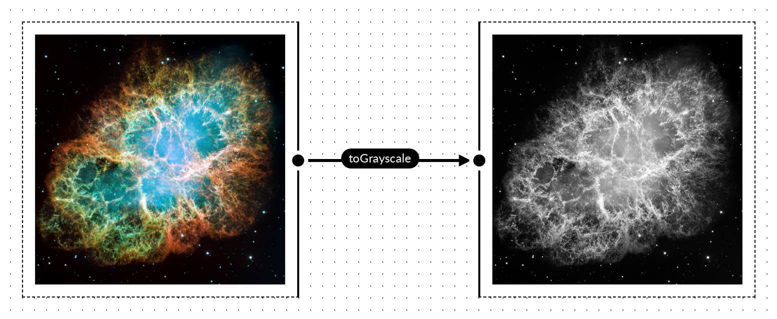
I did some quick benchmarking with canvas-image-transformer, looking at the performance between directly manipulating pixels on a 2D canvas versus using a fragment shader on a WebGL canvas. For testing, I used a grayscale transformation as it can be done with a simple weighted sum (R*0.2126 + G*0.7152 + B*0.0722) and there’s a high degree of parity between the fragment shader code and the code for pixel operations on a 2D canvas.

Converting to grayscale

Pixel operations on the 2D canvas are as follows:

for(var i=0; i<pixels.data.length; i+=4) { var grayPixel = parseInt(((0.2126*(pixels.data[i]/255.0)) + (0.7152*(pixels.data[i+1]/255.0)) + (0.0722*(pixels.data[i+2]/255.0))) * 255.0); pixels.data[i] = grayPixel; pixels.data[i + 1] = grayPixel; pixels.data[i + 2] = grayPixel; }

The corresponding fragment shader for the WebGL canvas is as follows:

precision mediump float; uniform sampler2D uSampler; varying vec2 vTextureCoord; void main(void) { vec4 src = texture2D( uSampler, ( vTextureCoord ) ); float grayPx = src.r*0.2126 + src.g*0.7152 + src.b*0.0722; gl_FragColor = vec4(grayPx, grayPx, grayPx, 1); }

Performance comparisons in Chrome

Here’s the setup for comparing performance of the 2 method:

  • Input was a 3864×3864 image of the Crab Nebula, rendered onto a 2D canvas (note that time to render onto the 2D canvas is not considered in the data points below)
  • Output is the 2D canvas that the input image was render on
  • CPU was an AMD Ryzen 7 5700X
  • GPU was a RTX 2060
  • OS is Windows 10 Build 19044
  • Browser is Chrome 108.0.5359.125
  • Hard refresh on page load to bypass any browser-level caching
  • Transformation via WebGL approach for 25 iterations
  • Transformation via 2D canvas approach for 25 iterations

Visually, this is what’s being done:

canvas-image-transformer grayscale conversion

I tried to eliminate as much background noise as possible from the result; that is, eliminating anything that may have a impact on CPU or GPU usage: closing other applications that may have significant usage, not having any other tabs open in the browser, and not having DevTools open when image processing was being done. That said, I was not rigorous about this and the numbers presented are to show overall/high-level behavior and performance; they’re not necessarily representative of what peak performance would be on the machine or browser.

It’s also worth noting that canvas-image-transformer doesn’t attempt to do any sort of caching in the first iteration (i.e. textures are re-created, shaders are re-compiled, etc. on each iteration), so we shouldn’t expect large variances in performance from one iteration to the next.

Graphing the data points for each approach, for each iteration, I got the following (note that what’s presented is just the data for 1 test run; I did test multiple times and consistently saw the same behavior but, for simplicity, I just graphed the values from 1 test run):

canvas-image-transformer performance data

So, the data points for the first iteration are interesting.

  • On the 2d canvas, the transformation initially takes 371.8ms
  • On the webgl2, the transformation initially takes 506.5ms

That’s a massive gap in performance between the 2 methods, with the 2d canvas method being significantly faster. I would have expected the WebGL approach to be faster here as, generally, graphics-related things would be faster with a lower-level GPU interface, but that’s clearly not the case here.

For subsequent iterations, we can see that performance improves and normalizes for both approaches, with significantly better performance using the WebGL approach; however, why don’t we see this sort of performance during the first iteration? Profiling the code, I noticed I was consistently seeing the majority of execution time spent on texImage2D() during the first iteration:

gl.texImage2D(gl.TEXTURE_2D, 0, gl.RGBA8, gl.RGBA, gl.UNSIGNED_BYTE, srcCanvas);

Looking at the execution time of texImage2D() across iterations, we get the following:

canvas-image-transformer texImage2D execution time

We see 486.9ms spent in texImage2D() during the first iteration but then execution time drops to only ~0.1ms in subsequent iterations. It’s clear that loading data into a texture is the most costly operation on the first iteration, however it looks like there’s some sort of caching mechanism, likely in Chrome’s GPU component, that essentially eliminates this cost on subsequent iterations.

In an attempt to optimize the call in the first iteration, I briefly looked into potential optimizations to the texImage2D() call but didn’t find much. There’s no mipmap creation or doing any sort of format conversion here, so we’re just bound by how quickly we can get the pixels into VRAM.

Normal refresh (after previous page load)

There’s a bit more nuance here that’s worth touching on. Looking at just the first iteration in Chrome, after normal/soft refreshes, we see some interesting behavior:

canvas-image-transformer performance data, first iteration only
  • For the 2d canvas, the first iteration transformation times look the same as when doing a hard refresh
  • For the WebGL canvas, we’re getting the transformation times we saw after the first iteration when doing a soft refresh!

It looks like Chrome’s texture caching mechanism is in play and preserves cache entries across soft page refreshes.

What about Firefox and other browsers?

I would expect most Webkit-based browsers would have similar behavior to what’s in Chrome and some quick testing in Edge confirms this.

Firefox is a different beast. Testing in Firefox 108.0.2, we see the following transformation times:

canvas-image-transformer performance data

Performance, overall, is much more consistent than in Chrome, but not always better.

  • For the 2d canvas method, performance is simply worse; on the first iteration we see transformations take 150+ milliseconds more than in Chrome, and on subsequent iterations the performance gap is even wider.
  • For the WebGL method, our first iteration performance is significantly better than Chrome, reduced by more than 175 milliseconds. However, on subsequent iterations we don’t see the drastic performance improvement we see in Chrome.

For the 2d canvas method, it’s hard to say why it performs so differently than Chrome. However, for the WebGL method, a bit of profiling led to some interesting insights. In Firefox, the execution time of texImage2D() is consistent across iterations, hovering ~40ms; this means it performs significantly better than Chrome’s worst case (first iteration) and significantly worse than Chrome’s best case (non-first iteration where execution time is below 0.1ms), as shown below.

canvas-image-transformer performance data

The other significant aspect to Firefox’s performance is in the performance of the Canvas drawImage() call, in drawing from a WebGL canvas to a 2D canvas. At the tail end of the transformation process, canvas-image-transformer does the following:

const srcCtx = srcCanvas.getContext('2d'); srcCtx.drawImage(glCanvas, 0, 0, srcCanvas.width, srcCanvas.height);

Basically, it’s taking what’s on the WebGL canvas and writing it out to the input/source canvas, which is a 2D canvas. In Chrome this is a very fast operation, typically less that 2ms, in Firefox I see this typically going above 200ms.

canvas-image-transformer performance data

Firefox consistency

Finally, looking at transformation times across soft refreshes, we see Firefox performance is very consistent for both the 2D canvas and WebGL method:

canvas-image-transformer performance data

However, I did encounter a case where WebGL performance was more erratic. This was testing when I had a lot of tabs open and I suspect there was some contention for GPU resources.

Takeaways

There’s perhaps a number of small insights here depending on use-case and audience, but there’s 2 significant high-level takeaways for me:

  • GPUs are very fast at parallel processing but loading data to be processed and retrieving the processed data can be expensive operations
  • It’s worthwhile to measure things; I was fairly surprised by the different performance profiles between Firefox and Chrome

Pushing computation to the front: thumbnail generation

Frontend possibilities

As the APIs brought forward by HTML5 about a decade ago have matured and the devices running web browsers have continued to improve in computational power, looking at what’s possible on the frontend and the ability to bring backend computations to the frontend has been increasingly interesting to me. Such architectures would see each user’s browsers as a worker for certain tasks and could simply backend systems, as those tasks are pushed forward to the client. Using Canvas for image processing tasks is one area that interesting and that I’ve had success with.

For Mural, I did the following Medium-esque image preload effect, the basis of which is generating a tiny (16×16) thumbnail which is loaded with the page. That thumbnail is blurred via CSS filter, and transitions to the full-resolution image once it’s loaded. The thumbnail itself is generated entirely on the frontend when a card is created and saved alongside the card data.

In this post, I’ll run though generating and handling that 16×16 thumbnail. This is fairly straightforward use of the Canvas API, but it does highlight how frontend clients can be utilized for operations typically relegated to server-side systems.

The image processing code presented is encapsulated in the canvas-image-transformer library.

<img> → <canvas>

A precursor for any sort of image processing is getting the image data into a <canvas>. The <img> element and corresponding HTMLImageElement interface don’t provide any sort of pixel-level read/write functionality, whereas the <canvas> element and corresponding HTMLCanvasElement interface does. This transformation is pretty straightforward:

The code is as follows (an interesting thing to note here is that this can all be done without injecting anything into the DOM or rendering anything onto the screen):

const img = new Image(); img.onload = function() { const canvas = document.createElement('canvas'); canvas.width = img.width; canvas.height = img.height; const canvasCtx = canvas.getContext('2d'); canvasCtx.drawImage(img, 0, 0, img.width, img.width); // the image has now been rendered onto canvas } img.src = "https://some-image-url";

Resizing an image

Resizing is trivial, as it can be handled directly via arguments to CanvasRenderingContext2D.drawImage(). Adding in a bit of math to do proportional scaling (i.e. preserve aspect ratio), we can wrap the transformation logic into the following method:

/** * * @param {HTMLImageElement} img * @param {Number} newWidth * @param {Number} newHeight * @param {Boolean} proportionalScale * @returns {Canvas} */ imageToCanvas: function(img, newWidth, newHeight, proportionalScale) { if(proportionalScale) { if(img.width > img.height) { newHeight = newHeight * (img.height / img.width); } else if(img.height > img.width) { newWidth = newWidth * (img.width / img.height); } else {} } var canvas = document.createElement('canvas'); canvas.width = newWidth; canvas.height = newHeight; var canvasCtx = canvas.getContext('2d'); canvasCtx.drawImage(img, 0, 0, newWidth, newHeight); return canvas; }

Getting the transformed image from the canvas

My goto method for getting the data off a canvas and into a more interoperable form is to use the HTMLCanvasElement.toDataURL() method, which allows easily getting the image as a PNG or JPEG. I do have mixed feeling about data-URIs; they’re great for the web, because so much of the web is textually based, but they’re also horribly bloated and inefficient. In any case, I think interoperability and ease-of-use usually wins out (esp. here where we’re dealing with a 16×16 thumbnail and the data-uri is relatively lightweight) and getting a data-uri is generally the best solution.

Using CanvasRenderingContext2D.getImageData() to get the raw pixel from a canvas is also an option but, for a lot of use-cases, you’d likely need to compress and/or package the data in some way to make use of it.

Save the transformed image

With a data-uri, saving the image is pretty straightforward. Send it to the server via some HTTP method (POST, PUT, etc.) and save it. For a 16×16 PNG the data-uri textual representation is small enough that we can put it directly in a relational database and not worry about a conversion to binary.

Alternatives & limitations

The status quo alternative is having this sort of image manipulation logic encapsulated within some backend component (method, microservice, etc.) and, to be fair, such systems work well. There’s also some very concrete benefits:

  • You are aware of and have control over the environment in which the image processing is done, so you’re isolated from browser quirks or issues stemming from a user’s computing environment.
  • You have an easier path for any sort of backfill (e.g. how do you generate thumbnails for images previously uploaded?) or migration needs (e.g. how can you move to a different sized thumbnail?); you can’t just run though rows in a database and make a call to get what you need.

However, something worth looking at is that backend systems and server-side environments are typically not optimized for any sort of graphics workload, as processing is centered around CPU cores. In contrast, the majority of frontend environments have access to a GPU, even fairly cheap phone have some sort of GPU that is better suited for “embarassing parallel”-esque graphics operations, the performance benefits of which you get for free with the Canvas API in all modern browsers.

In Chrome, see the output of chrome://gpu:

chrome settings, canvas hardware acceleration

Scale, complexity and cost also come into play. Thinking of frontend clients as computational nodes can change the architecture of systems. The need for server-side resources (hardware, VMs, containers, etc.) is eliminated. Scaling concerns are also, to a large extent, eliminated or radically changed as operations are pushed forward to the client.

Future work

What’s presented here is just scratching the surface of what’s possible with Canvas. WebGL also presents as a ton of possibilities and abstraction layers like gpu.js are really interesting. Overall, it’s exciting to see the web frontend evolve beyond a mechanism for user input and into a layer in which substantive computation can be done.

Using feColorMatrix to dynamically recolor icons (part 2, two-color icons)

Previously, I looked at how to use feColorMatrix to dynamically change the color of single-color icons. In this post, we’ll look at using feColorMatrix, feBlend, and feComposite to implement an algorithm that allow for dynamically changing the the colors of an icon with 2 colors.

The Algorithm

With a single color, we could think of the process as being a single step: applying the color transformation matrix with the desired R, G, B values. For two colors, there are multiple steps and matrices involved, so it’s worth having a high-level overview and conceptual understanding of the algorithm before delving into the details.

  • The input icon will have 2 color, black and white; black areas will be changed to colorA and white areas will be changed to colorB
  • Add colorA to the source image (black areas will take on the new color, white areas will remain white), the result is imageA
  • Invert the source image, then add colorB to it (black areas will become white and remain white, white areas will become black and take on the new color), the result is imageB
  • Combine imageA and imageB, such that the alpha component from the source image is preserved, output the result
Dynamically recolor two-color icon

Note that from the above, we see the key operations that are needed:

  • Add
  • Invert
  • Combine

Another look at the color transformation matrix for applying a single-color

Note that the transformation matrix used previously for the single-color case, only preserves the alpha component from the input. The R, G, and B components are thrown away:

[[0, 0, 0, 0, R], [0, 0, 0, 0, G], [0, 0, 0, 0, B], [0, 0, 0, 1, 0]][(R_(src)), (G_(src)), (B_(src)), (A_(src))] = [(R), (G), (B), (A_(src))]

It doesn’t matter what color the input pixel is, applying the transformation matrix will result in those Rsrc Gsrc Bsrc input values being multiplied by zero, before the new/output R, G, B values are added in.

While this is fine for the single-color case, for the two-color algorithm to work, the distinction between the black areas and the white areas need to be kept intact, so we have to work with the Rsrc Gsrc Bsrc values from the input vector and preserve the distinction.

Making Rsrc Gsrc Bsrc part of the transformation

Modifying the transformation matrix to allow Rsrc Gsrc Bsrc to be part of the calculations requires the first 3 diagonal elements of the matrix to be non-zero.

The simplest case of this is the identity matrix:

[[1, 0, 0, 0, 0], [0, 1, 0, 0, 0], [0, 0, 1, 0, 0], [0, 0, 0, 1, 0]][(R_(src)), (G_(src)), (B_(src)), (A_(src))] = [(R_(src)), (G_(src)), (B_(src)), (A_(src))]

Let’s look at a few matrices that define transformations needed for the algorithm.

The add colorK matrix:

[[1, 0, 0, 0, R_(k)], [0, 1, 0, 0, G_(k)], [0, 0, 1, 0, B_(k)], [0, 0, 0, 1, 0]][(R_(src)), (G_(src)), (B_(src)), (A_(src))] = [(R_(src) + R_(k)), (G_(src) + G_(k)), (B_(src) + B_(k)), (A_(src))]

The invert matrix:

[[-1, 0, 0, 0, 1], [0, -1, 0, 0, 1], [0, 0, -1, 0, 1], [0, 0, 0, 1, 0]][(R_(src)), (G_(src)), (B_(src)), (A_(src))] = [(-R_(src) + 1), (-G_(src) + 1), (-B_(src) + 1), (A_(src))]

The above can be combined into a single transformation matrix, the invert & add colorK matrix:

[[-1, 0, 0, 0, 1 + R_(k)], [0, -1, 0, 0, 1 + G_(k)], [0, 0, -1, 0, 1 + B_(k)], [0, 0, 0, 1, 0]][(R_(src)), (G_(src)), (B_(src)), (A_(src))] = [(-R_(src) + 1 + R_(k)), (-G_(src) + 1 + G_(k)), (-B_(src) + 1 + B_(k)), (A_(src))]

Putting aside and referencing intermediate results

Note that the algorithm requires us to create 2 independent images (imageA and imageB) and then subsequently combine them.

This can be accomplished by utilizing the result attribute available on SVG filter primitive elements. By specifying a result identifier we are able to apply a transformation and put aside the resultant image.

Combining the intermediate results

Combining intermediate results/images can’t be done with feColorMatrix, it’s simply not an operation that can be constructed as a transformation. To handle this, SVG provides the feBlend element with a number of predefined operations available via the mode attribute. Based on the color transformations done to create imageA and imageB (mainly that the areas that are not of concern, the background, are set to white [1,1,1]), the multiply operation will work to combine the images (not perfectly, there’s one big problem with the alpha channel, but we’ll deal with that in a bit).

image multiply
<feBlend 
    color-interpolation-filters="linearRGB"
    in="imageA" 
    in2="imageB" 
    mode="multiply" 
    result="output" />        

The alpha channel problem

While feBlend seem to accomplish what’s needed, for anything other than a white background you’ll notice a white-ist outline around elements in the image, as you can see below.

alpha channel problems with feBlend

The problem is that for what we’re trying to accomplish we just want to simply preserve the alpha channel, not blend it in any way. However, all feBlend operations will perform a blend of the alpha channel. From the SVG spec:

image multiply

So there’s no way we can really work with feBlend to get a solution for the alpha channel, but we do have an idea of what the solution is: copy the alpha channel from the source image.

Fixing the alpha channel

Fixing the alpha channel will involve 2 steps:

  • For the image outputted by feBlend, get the alpha value to be 1 for every pixel
    (the reason this step will become apparent once we look at how feComposite has to be used)
  • Use feComposite to construct an image with the alpha values from the source image and the R,G,B values from the image outputted by feBlend

The first step is simple. We just need a slight modification to the 2 color transformation matrices used, such that one or both set the alpha channel to 1 for every pixel (note from the alpha blending equation, this will effectively set the alpha value to 1 for every pixel in the output). The modified matrices are shown below and it’s a good point to start showing some code.

The full-alpha add colorK matrix:

[[1, 0, 0, 0, R_(k)], [0, 1, 0, 0, G_(k)], [0, 0, 1, 0, B_(k)], [0, 0, 0, 0, 1]][(R_(src)), (G_(src)), (B_(src)), (A_(src))] = [(R_(src) + R_(k)), (G_(src) + G_(k)), (B_(src) + B_(k)), (1) ]

<feColorMatrix in="SourceGraphic" type="matrix" result="imageA"
    values="1 0 0 0 0
            0 1 0 0 0.68235294117
            0 0 1 0 0.93725490196
            0 0 0 0 1" /> 

The full-alpha invert & add colorK matrix:

[[-1, 0, 0, 0, 1 + R_(k)], [0, -1, 0, 0, 1 + G_(k)], [0, 0, -1, 0, 1 + B_(k)], [0, 0, 0, 0, 1]][(R_(src)), (G_(src)), (B_(src)), (A_(src))] = [(-R_(src) + 1 + R_(k)), (-G_(src) + 1 + G_(k)), (-B_(src) + 1 + B_(k)), (1)]

<feColorMatrix in="SourceGraphic" type="matrix" result="imageA"
    values="-1 0 0 0 1.0784313725
            0 -1 0 0 1.7058823529
            0 0 -1 0 1.2431372549
            0 0 0 0 1" />

For the next and final step, we need to take a look at feComposite.

The feComposite filter primitive allows for more fine-grained operations on pixels using the supported “arithmetic” operation:

feComposite arithmetic operation

As this operation is done on every channel, including the alpha channel, we have way to control what happens to the alpha pixels in a composition of 2 images.

We’re going to make use of this by:

  • Using an feColorMatrix, where the input in the source image, and transforming such that R,G,B is white [1,1,1] and the alpha remains unchanged
  • Using feComposite to do a simple arithmetic multiply (k1=1, k2=0, k3=0, k4=0), between the image constructed above (where R,G,B is [1,1,1] and alpha is the alpha from the source image) and the output from feBlend (where the R,G,B = the values we want for the output and alpha = 1)

Effectively, the source alpha is multiplied by 1 (as the image produced from the feBlend operation has the alpha set to 1 for all pixels) and the R,G,B values from the feBlend output are multiplied by 1 (as the constructed image, in the first step above, sets R,G,B to 1 for every pixel).

<!-- Get and use alpha from source image -->
<feColorMatrix in="SourceGraphic" type="matrix" result="whiteAlpha"
    values="0 0 0 0 1
            0 0 0 0 1
            0 0 0 0 1
            0 0 0 1 0" />     

<feComposite in="whiteAlpha" in2="outputFullAlpha" operator="arithmetic" k1="1" k2="0" k3="0" k4="0" />

Pulling everything together

We now have all the pieces for the filter and here’s what the code looks like:

<svg style="width:0; height:0; margin:0; padding:0; border:none;">
    <filter color-interpolation-filters="sRGB" id="colorTransformFilter">

        <feColorMatrix in="SourceGraphic" type="matrix" result="imageA"
            values="1 0 0 0 0
                    0 1 0 0 0.68235294117
                    0 0 1 0 0.93725490196
                    0 0 0 0 1" /> 

        <feColorMatrix in="SourceGraphic" type="matrix" result="imageB"
            values="-1 0 0 0 1.0784313725
                    0 -1 0 0 1.7058823529
                    0 0 -1 0 1.2431372549
                    0 0 0 0 1" />              
                    
        <feBlend 
            color-interpolation-filters="linearRGB"
            in="imageA" 
            in2="imageB" 
            mode="multiply" 
            result="outputFullAlpha" />        

        <!-- Get and use alpha from source image -->
        <feColorMatrix in="SourceGraphic" type="matrix" result="whiteAlpha"
            values="0 0 0 0 1
                    0 0 0 0 1
                    0 0 0 0 1
                    0 0 0 1 0" />     

        <feComposite in="whiteAlpha" in2="outputFullAlpha" operator="arithmetic" k1="1" k2="0" k3="0" k4="0" />

    </filter>
</svg>

The demo below uses the filter, along with a bit of Javascript to cycle and update the input colors (i.e. dynamically updating the values plugged into the first 2 feColorMatrix elements):

Limitations

We have the same limitations I mentioned in part 1:

  • For icons applied as background-images, the CSS filter property isn’t ideal. CSS filter will effect not only the element it’s applied to, but all child elements as well
  • As is the case with mixing the CSS filter property and the SVG filter element, effects governed by the CSS transition property won’t work

In addition, because of how the alpha channel in treated in regards to feBlend (setting all pixels to have alpha=1), you more than likely won’t get good results if the icon has different-colored adjoining or overlapping elements, as you won’t get a smooth transition at the edges/boundaries.

Using feColorMatrix to dynamically recolor icons (part 1, single-color icons)

I’ve been experimenting with using feColorMatrix as an elegant way to dynamically color/re-color SVG icons. Here I’ll look at working with single-color icons.

Working directly with the SVG markup

Changing the stroke and/or fill colors of the SVG elements directly can be a good solution in many cases, but it requires:

  • Placing the SVG markup into the document to query and modify the appropriate elements when a color update is needed (note that this option isn’t viable if you need to place the icon in an <img> tag or it needs to be placed as a background-image on an element, as you can’t reference the SVG element in such cases)
  • Treating the SVG markup as a templated, Javascript, string to make a data-URI, and re-making it when a color update is needed

By using the color transformation matrix provided by feColorMatrix these restrictions go away and we also get back the flexibility of using external files.

Icon color

Keep in mind, we’re only dealing with single-color icons. What color is used doesn’t technically matter, but black is a nice basis and in an actual project, black is beneficial, as you’re able to open your the icon files in an editor or browser and actually see it.

black colored icon

A black pixel within the icon can then be represented by the following vector:

black pixel as column vector

Note that the alpha component may vary due to antialiasing (to smooth out edges) or some translucency within the icon.

The color transformation matrix

feColorMatrix allows you to define a 5×4 transformation matrix. There’s a lot you can do with that, but note that the last column of the matrix is essentially an additive component for each channel (see matrix-vector multiplication), so in that column we enter the desired R, G, B values from top to bottom, which will be added to the zeros in the input vector. Next, we want to preserve the alpha component from the input vector, so the fourth column of the matrix becomes [0, 0, 0, 1]T and the fourth row of the last column is zero, as we don’t want to add anything to the alpha component.

color transformation matrix, [[0, 0, 0, 0, R], [0, 0, 0, 0, G], [0, 0, 0, 0, B], [0, 0, 0, 1, 0]][(0), (0), (0), (A_(src))] = [(R), (G), (B), (A_(src))]

The matrix-vector multiplication gives a new vector (that defines the output pixel) with the entered R, G, B values and the alpha value from the source pixel.

Representing the matrix within an feColorMatrix element is straightforward…

<feColorMatrix in="SourceGraphic" type="matrix"
values="0 0 0 0 R
0 0 0 0 G
0 0 0 0 B
0 0 0 1 0"
/>

… just plug in values for R, G, B.

Applying the color transformation

The color transformation matrix can be applied to an element by wrapping it in an SVG filter element and referencing the filter via the CSS filter property.

With Javascript, the values attribute of the feColorMatrix element can be updated dynamically. The color change will, in turn, be reflected in any elements referencing the SVG filter.

<!DOCTYPE html>
<html>
<body>
<!--
The values of the color matrix defines the color transformation what will be applied.
Here we just setup the elements and define an identity matrix. We'll modify the matrix via Javascript code
to define an actual color transformation.
-->
<svg style="width:0; height:0; margin:0; padding:0; border:none;">
<filter
color-interpolation-filters="sRGB" id="colorTransformFilter">
<feColorMatrix
in="SourceGraphic" type="matrix"
values="1 0 0 0 0
0 1 0 0 0
0 0 1 0 0
0 0 0 1 0"
/>

</filter>
</svg>

<!--
Element with an SVG icon that we want to colorize
Note: that the color transformation is applied to everything not only to the background, but everything
within the element as well.

Typical solution to to isolate background stuff to it's own div and use another div for contents

-->
<div id="logo-colored"
style="
width:300px;
height:300px;
background-color: transparent;
background-image: url(logo.svg);
background-position: center center;
background-repeat: no-repeat;
background-size: cover;
filter:url(#colorTransformFilter);"
>

<p
style="color:#fff">Testing 1 2 3...</p>
</div>

<script
type="text/javascript">
/**
* A little helper function to update the color transformation matrix
*
* @param {Number} _r
* @param {Number} _g
* @param {Number} _b
*/
const setPrimaryColor = function(_r, _g, _b) {

const rScaled = _r / 255.0;
const gScaled = _g / 255.0;
const bScaled = _b / 255.0;

const feColorMatrixElem = document.getElementById('colorTransformFilter').getElementsByTagName('feColorMatrix')[0];
feColorMatrixElem.setAttribute(
`values`,
`0 0 0 0 ${rScaled}
0 0 0 0 ${gScaled}
0 0 0 0 ${bScaled}
0 0 0 1 0`
);
};

// Set/update color transformation matrix
setPrimaryColor(129, 0, 0);
</script>

</body>
</html>

The code will take a black-colored icon and re-color it to [129, 0, 0], as seen below:

Limitations

This technique provides a lot of flexibility, but it’s not without it’s limits.

  • For icons applied as background-images, the CSS filter property isn’t ideal. CSS filter will effect not only the element it’s applied to, but all child elements as well. Note the “Testing 1 2 3…” paragraph is re-colored in the demo above.
  • As is the case with mixing the CSS filter property and the SVG filter element, effects governed by the CSS transition property won’t work.

Similar techniques

  • For shifting between colors, the hue-rotate() CSS filter function can be a solution. However, in practice, I don’t find this intuitive and color changes are rarely just hue rotations.
  • A more limited case, transitioning a colored icon to white, can be achieved with 2 CSS filter functions, brightness(0) and invert(100%).
  • You can do crazier things by trying to compute and fit a solution to the hue-rotation, saturation, sepia, and invert filter functions; however this is both complex to grasp and produces inexact/approximate color matches.
  • An SVG filter using feComponentTransfer should work, but I don’t find it as intuitive to work with.

Resources

If you want to interactively play around with feColorMatrix, check out SVG Color Filter Playground.

Encoding MP4s in the browser

Is this possible?

Given that it’s relatively easy to access a camera and capture frames within a browser, I began wondering it there was a way to encode frames and create a video within the browser as well. I can see a few benefits to doing this, perhaps the biggest being that you can move some very computationally expensive work to front-end, avoiding the need to setup and scale a process to do this server-side.

I searched a bit and first came across Whammy as a potential solution, which take a number of WebP images and creates a WebM video. However, only Chrome will let you easily get data from a canvas element as image/webp (see HTMLCanvasElement.toDataURL docs). The non-easy way is to read the pixel values from the canvas element and encode them as WebP. However, I also couldn’t find any existing JS modules that did this (only a few NodeJS wrappers for the server-side cwebp application) and writing an encoder was a much bigger project that I didn’t want to undertake.

The other option I came across, and used, was ffmpeg.js. This is a really interesting project, it’s a port of ffmpeg via Emscripten to JS code which can be run in browsers that support WebAssembly.

Grabbing frames

My previous post on real-time image processing covers how to setup the video stream, take a snapshot, and render it to a canvas element. To work with ffmpeg.js, you’ll additionally need the frame’s pixels from the canvas element as a JPEG image, represented as bytes in a Uint8Array. This can be done as follows:

var dataUri = canvas.toDataURL("image/jpeg", 1);
var jpegBytes = convertDataURIToBinary(dataUri);

convertDataURIToBinary() is the following method, which will take the data-uri representation of the JPEG data and transform it into a Uint8Array:

function convertDataURIToBinary(dataURI) {
var base64 = dataURI.substring(23);
var raw = window.atob(base64);
var rawLength = raw.length;

var array = new Uint8Array(new ArrayBuffer(rawLength));
for (i = 0; i < rawLength; i++) {
array[i] = raw.charCodeAt(i);
}
return array;
};

FYI, this is just a slight modification of a method I found in this gist.

Note that I did not use PNG images due to an issue in the current version of ffmpeg.js (v3.1.9001).

Working with ffmpeg.js

ffmpeg.js comes with a Web Worker wrapper (ffmpeg-worker-mp4.js), which is really nice as you can run “ffmpeg –whatever” by just posting a message to the worker, and get the status/result via messages posted backed to the caller via Worker.onmessage.

var worker = new Worker("node_modules/ffmpeg.js/ffmpeg-worker-mp4.js");
worker.onmessage =
function (e) {
var msg = e.data;

switch (msg.type) {
case "ready":
console.log(
'mp4 worker ready');
break;
case "stdout":
console.log(msg.data);
break;
case "stderr":
console.log(msg.data);
break;

case "done":
var blob = new Blob([msg.data.MEMFS[0].data], {
type:
"video/mp4"
});

// ...
break;

case "exit":
console.log(
"Process exited with code " + msg.data);
break;
}
};

Input and output of files is handled by MEMFS (one of the virtual file systems supported by Emscripten). On the “done” message from ffmpeg.js, you can access the output files via the msg.data.MEMFS array (shown above). Input files are specified via an array in the call to worker.postMessage (shown below).

worker.postMessage(
{
type:
"run",
TOTAL_MEMORY: 268435456,
MEMFS: [
{
name:
"input.jpeg",
data: jpegBytes
}
],
arguments: [
"-r", "60", "-i", "input.jpeg", "-aspect", "16/9", "-c:v", "libx264", "-crf", "1", "-vf", "scale=1280:720", "-pix_fmt", "yuv420p", "-vb", "20M", "out.mp4"]
}
);

Limitations

With a bunch of frames captured from the video stream, I began pushing them through ffmpeg.js to encode a H.264 MP4 at 720p, and things started to blow up. There were 2 big issues:

  • Video encoding is no doubt a memory intensive operation, but even for a few dozen frames I could never give ffmpeg.js enough. I tried playing around with the TOTAL_MEMORY prop in the worker.postMessage call, but if it’s too low ffmpeg.js runs out of memory and if it’s too high ffmpeg.js fails to allocate memory.
  • Browser support issues. Support issues aren’t surprising here given that WebAssembly is still experimental. The short of it is: things work well in Chrome and Firefox on desktop. For Edge or Chrome on a mobile device, things work for a while before the browser crashes. For iOS there is no support.

Hacking something together

The browser issues were intractable, but support on Chrome and Firefox was good enough more me, and I felt I could work around the memory limitations. Lowering the memory footprint was a matter of either:

  • Reducing the resolution of each frame
  • Reducing the number of frames

I opted for the latter. My plan was to make a small web application to allow someone to easily capture and create time-lapse videos, so I had ffmpeg.js encode just 1 frame to a H.264 MP4, send that MP4 to the server, and then use ffmpeg’s concat demuxer on the server-side to progressively concatenate each individual MP4 file into a single MP4 video. What this enables is for the more costly encoding work to the done client-side and the cheaper concatenation work to be done server-side.

Time Stream was the end result.

Here’s a time-lapse video created using an old laptop and a webcam taped onto my balcony:

This sort of hybrid solution works well. Overall, I’m happy with the results, but would love the eliminate the server-side ffmpeg dependency outright, so I’m looking forward to seeing Web Assembly support expand and improve across browsers.

More generally, it’s interesting to push these types of computationally intensive tasks to the front-end, and I think it presents some interesting possibilities for architecting and scaling web applications.

Brute-force convex hull construction

I’ve been experimenting a bit with convex hull constructions and below I’ll explain how to do a brute-force construction of a hull.

It’s worth noting up-front that the brute-force method is slow, O(n3) worst case complexity. So why bother? I think there are a few compelling reasons:

  • The brute-force method expresses the fundamental solution, which gives you the basic building blocks and understanding to approach more complex solutions
  • It’s faster to implement
  • It’s still a viable solution when n is small, and n is usually small.

What is a convex hull?

You can find a formal definition on Wikipedia. Informally, and specific to computational geometry, the convex hull is a convex polygon in which all points are either vertices of said polygon or enclosed within the polygon.

Brute-force construction

  • Iterate over every pair of points (p,q)
  • If all the other points are to the right (or left, depending on implementation) of the line formed by (p,q), the segment (p,q) is part of our result set (i.e. it’s part of the convex hull)

Here’s the top-level code that handles the iteration and construction of resulting line segments:

/**
* Compute convex hull
*/
var computeConvexHull = function() {
console.log(
"--- ");

for(var i=0; i<points.length; i++) {
for(var j=0; j<points.length; j++) {
if(i === j) {
continue;
}

var ptI = points[i];
var ptJ = points[j];

// Do all other points lie within the half-plane to the right
var allPointsOnTheRight = true;
for(var k=0; k<points.length; k++) {
if(k === i || k === j) {
continue;
}

var d = whichSideOfLine(ptI, ptJ, points[k]);
if(d < 0) {
allPointsOnTheRight =
false;
break;
}
}

if(allPointsOnTheRight) {
console.log(
"segment " + i + " to " + j);
var pointAScreen = cartToScreen(ptI, getDocumentWidth(), getDocumentHeight());
var pointBScreen = cartToScreen(ptJ, getDocumentWidth(), getDocumentHeight());
drawLineSegment(pointAScreen, pointBScreen);
}

}
}
};

The “secret sauce” is the whichSideOfLine() method:

/**
* Determine which side of a line a given point is on
*/
var whichSideOfLine = function(lineEndptA, lineEndptB, ptSubject) {
return (ptSubject.x - lineEndptA.x) * (lineEndptB.y - lineEndptA.y) - (ptSubject.y - lineEndptA.y) * (lineEndptB.x - lineEndptA.x);
};

This is a bit of linear algebra derived from the general equation for a line.

The result represents the side of a line a point is one, based on the sign of the result. We can check if the point is on the left or on the right, it doesn’t matter as long as there is consistency and the same check is done for all points.

How it looks

I made a few diagrams to show the first few steps in the algorithm, as segments constituting the convex hull are found. The shaded area represents our success case, where all other points are to the right of the line formed by the points under consideration. Not shown are the failure cases (i.e. one or more points are on the left of the line formed by the points under consideration).

convex hull construction, brute force, step 1

convex hull construction, brute force, step 1

convex hull construction, brute force, step 1

Code and Demo

You can play around with constructing a hull below by double-clicking to add vertices.

You can find the code on GitHub.

Post-process shaders in glfx

Pushed an update to glfx to allow for post-process shading. When a post-process shader is defined, the scene is rendered to a screen-space quad (the size of the viewport), and that quad is then rendered to the viewport with the post-process shader applied.

The shader is loaded (asynchronously) like any other:

glfx.shaders.load('screenspace.fs', "frag-shader-screenspace", glfx.gl.FRAGMENT_SHADER);

Once loaded, we create the shader program, and get locations for whatever variables are used. The vertex shader isn’t anything special, it just transforms a vertex by the model-view and projection matrices, and passes along the texture coordinates.

glfx.whenAssetsLoaded(function() {

var postProcessShaderProgram = glfx.shaders.createProgram([glfx.shaders.buffer['vert-shader-basic'], glfx.shaders.buffer['frag-shader-screenspace']],
function(_shprog) {

// Setup variables for shader program
_shprog.vertexPositionAttribute = glfx.gl.getAttribLocation(_shprog, "aVertexPosition");
_shprog.pMatrixUniform = glfx.gl.getUniformLocation(_shprog,
"uPMatrix");
_shprog.mvMatrixUniform = glfx.gl.getUniformLocation(_shprog,
"uMVMatrix");
_shprog.textureCoordAttribute = glfx.gl.getAttribLocation(_shprog,
"aTextureCoord");

_shprog.uPeriod = glfx.gl.getUniformLocation(_shprog,
"uPeriod");
_shprog.uSceneWidth = glfx.gl.getUniformLocation(_shprog,
"uSceneWidth");
_shprog.uSceneHeight = glfx.gl.getUniformLocation(_shprog,
"uSceneHeight");

glfx.gl.enableVertexAttribArray(_shprog.vertexPositionAttribute);
glfx.gl.enableVertexAttribArray(_shprog.textureCoordAttribute);

});

...

We then tell glfx to apply our post-process shader program:

glfx.scene.setPostProcessShaderProgram(postProcessShaderProgram);

This call will result in different rendering path, which renders the scene to a texture, applies that texture to a screen-space quad, and renders the quad with the post-process shader.

Here is the shader for screenspace.fs, used in the demo shown above:

precision mediump float;

uniform float uPeriod;
uniform float uSceneWidth;
uniform float uSceneHeight;
uniform sampler2D uSampler;        
varying vec2 vTextureCoord;

void main(void) {

vec4 sum = vec4( 0. );
float blurSampleOffsetScale = 2.8;
float px = (1.0 / uSceneWidth) * blurSampleOffsetScale;
float py = (1.0 / uSceneHeight) * blurSampleOffsetScale;

vec4 src = texture2D( uSampler, ( vTextureCoord ) );

sum += texture2D( uSampler, ( vTextureCoord + vec2(-px, 0) ) );
sum += texture2D( uSampler, ( vTextureCoord + vec2(-px, -py) ) );
sum += texture2D( uSampler, ( vTextureCoord + vec2(0, -py) ) );
sum += texture2D( uSampler, ( vTextureCoord + vec2(px, -py) ) );
sum += texture2D( uSampler, ( vTextureCoord + vec2(px, 0) ) );
sum += texture2D( uSampler, ( vTextureCoord + vec2(px, py) ) );
sum += texture2D( uSampler, ( vTextureCoord + vec2(0, py) ) );
sum += texture2D( uSampler, ( vTextureCoord + vec2(-px, py) ) );
sum += src;

sum = sum / 9.0;

gl_FragColor = src + (sum * 2.5 * uPeriod);

}

Note that it requires a few uniforms to be supplied to it, we use the glfx.scene.onPostProcessPreDraw() callback to setup the variables (before the post-processed scene is drawn):

var timeAcc = 0;
glfx.scene.onPostProcessPreDraw =
function(tdelta) {

timeAcc += tdelta;
var timeScaled = timeAcc * 0.00107;

if(timeScaled > 2.0*Math.PI) {
timeScaled = 0;
timeAcc = 0;
}

var period = Math.cos(timeScaled);
glfx.gl.uniform1f(postProcessShaderProgram.uPeriod, period + 1.0);

glfx.gl.uniform1f(postProcessShaderProgram.uSceneWidth, glfx.gl.viewportWidth);
glfx.gl.uniform1f(postProcessShaderProgram.uSceneHeight, glfx.gl.viewportHeight);
};

What we’re doing is using the scene rendering time deltas to generate a periodic/sinusoidal wave. This results in the pulsing brightness/fading effect of the scene. The brightness effect itself is done by adding the source pixel to a blurred + brightened version of itself. The blurring allows for the soft fade in and fade out.

GLSL variable qualifiers

I’ve been playing around with WebGL shader code recently and found this bit on variable prefixes helpful, particularly in the explanation of the variable qualifiers:

  • Attribute: data provided by buffers
  • Uniform: inputs to the shaders
  • Varying: values passed from a vertex shader to a fragment shader and interpolated (or varied) between the vertices for each pixel drawn

Something important to keep in mind is that this relates to the OpenGL ES Shading Language, Version 1.00, which is (unfortunately) what’s currently supported by WebGL.

A WebGL implementation must only accept shaders which conform to The OpenGL ES Shading Language, Version 1.00 [GLES20GLSL], and which do not exceed the minimum functionality mandated in Sections 4 and 5 of Appendix A.

Attribute and Varying were part of early versions of, OpenGL-supported, GLSL, but are deprecated as of OpenGL 3.0 / GLSL 1.30.10, and replaced with more generic constructs:

  • in is for input from the previous pipeline stage, i.e. per vertex (or per fragment) values at most, per primitive if using glAttribDivisor and hardware instanciation
  • out is for output to the next stage

Real-time image processing on the web

A while ago I began playing around with grabbing a video stream from a webcam and seeing what I could do with the captured data. Capturing the video stream using the navigator.getUserMedia() navigator.mediaDevices.getUserMedia() method was straightforward, but directly reading and writing the image data of the video stream isn’t possible. That said, the stream data can be put onto a canvas using CanvasRenderingContext2D.drawImage(), giving you the ability to manipulate the pixel data.

const videoElem = document.querySelector('video'); // Request video stream navigator.mediaDevices.getUserMedia({video: true, audio: false}) .then(function(_videoStream) { // Render video stream on <video> element videoElem.srcObject =_videoStream; }) .catch(function(err) { console.log(`getUserMedia error: ${err}`); } ); const videoElem = document.querySelector('video'); const canvas = document.querySelector('canvas'); const ctx = canvas.getContext('2d'); // put snapshot from video stream into canvas ctx.drawImage(videoElem, 0, 0);

You can read and write to the <canvas> element, so hiding the <video> element with the source data and just showing the <canvas> element seems logical, but the CanvasRenderingContext2D.drawImage() call is expensive; looking at the copied stream on the <canvas> element there is, very noticeable, visual lag. Another reason to avoid this option is that the frequency at which you render (e.g. 30 FPS), isn’t necessarily the frequency at which you’d want to grab and process image data (e.g. 10 FPS). The disassociation allows you to keep the video playback smooth, for a better user experience, but more effectively utilize CPU cycles for image processing. At least in my experience so far, a small delay in visual feedback from image processing is acceptable and looks perfectly fine intermixed with the higher-frequency video stream.

So the best options all seem to involve showing the <video> element with the webcam stream and placing visual feedback on top of the video in some way. A few ideas:

  • Write pixel data to another canvas and render it on top of the <video> element
  • Render SVG elements on top of the <video> element
  • Render DOM elements (absolutely positioned) on top of the <video> element

The third option is an ugly solution, but it’s fast to code and thus allows for quick prototyping. The demo and code below shows a quick demo I slapped together using <div> elements as markers for hotspots, in this case bright spots, within the video.

Here’s the code for the above demo:

<!DOCTYPE html> <html> <head> <title>Webcam Cap</title> <meta charset="UTF-8"> <meta name="viewport" content="width=device-width, initial-scale=1.0"> <style type="text/css"> * { margin:0; padding:0; border:none; overflow:hidden; } </style> </head> <body> <div> <video style="width:640px; height:480px;" width="640" height="480" autoplay></video> <canvas style="display:none; width:640px; height:480px;" width="640" height="480"></canvas> </div> <div class="ia-markers"></div> <script type="text/javascript"> const videoElem = document.querySelector('video'); const canvas = document.querySelector('canvas'); const ctx = canvas.getContext('2d'); var snapshotIntv = null; const width = 640; const height = 480; // Request video stream navigator.mediaDevices.getUserMedia({video: true, audio: false}) .then(function(_videoStream) { // Render video stream on <video> element videoElem.srcObject =_videoStream; // Take a snapshot of the video stream 10ms snapshotIntv = setInterval(function() { processSnapshot(_videoStream); }, 100); }) .catch(function(err) { console.log(`getUserMedia error: ${err}`); } ); // Take a snapshot from the video stream function processSnapshot() { // put snapshot from video stream into canvas ctx.drawImage(videoElem, 0, 0); // Clear old snapshot markers var markerSetParent = (document.getElementsByClassName('ia-markers'))[0]; markerSetParent.innerHTML = ''; // Array to store hotzone points var hotzones = []; // Process pixels var imageData = ctx.getImageData(0, 0, width, height); for (var y = 0; y < height; y+=16) { for (var x = 0; x < width; x+=16) { var index = (x + y * imageData.width) << 2; var r = imageData.data[index + 0]; var g = imageData.data[index + 1]; var b = imageData.data[index + 2]; if(r > 200 && g > 200 && b > 200) { hotzones.push([x,y]); } } } // Add new hotzone elements to DOM for(var i=0; i<hotzones.length; i++) { var x = hotzones[i][0]; var y = hotzones[i][1]; var markerDivElem = document.createElement("div"); markerDivElem.setAttribute('style', 'position:absolute; width:16px; height:16px; border-radius:8px; background:#0f0; opacity:0.25; left:' + x + 'px; top:' + y + 'px'); markerDivElem.className = 'ia-hotzone-marker'; markerSetParent.appendChild(markerDivElem); } } </script> </body> </html>

Edit (8/1/2020): The code has been updated to reflect changes in the MediaDevices API. This includes:

  • navigator.getUserMedianavigator.mediaDevices.getUserMedia. The code structure is slightly different given that the latter returns a promise.
  • Assigning the media stream to a video element directly via the srcObject attribute. This is now required in most modern browsers as the old way of using createObjectURL on the stream and assigning the returned URL to the video element’s src attribute is no longer supported.

In addition, there’s also just some general code cleanup to modernize the code and make it a little easier to read. Some of the language in the post has also been tweaked to make things clearer.

WebGL on a high-DPI display

Dealing with WebGL on a high-DPI display isn’t too difficult, but it does require an understanding of device pixels vs CSS pixels. Elements on a page automatically upscale on a high-DPI display, as dimensions are typically defined with CSS, and therefore defined in units of CSS pixels. The <canvas> element is no exception. However, upscaling a DOM element doesn’t mean that the content within the element will be upscaled or rendered nicely – this is why non-vector content can appear blurry on higher resolutions. With WebGL content, not only will it appear blurry, but the viewport will likely be clipped as well, due to the viewport being incorrectly calculated using CSS pixel dimensions.

With WebGL everything is assumed to be in units of device pixels and there is no automatic conversion from CSS pixels to device pixels. To specify the device pixel dimensions of the <canvas>, we need to set the width and height attributes of the element:

CSS Pixels vs Device Pixels on canvas

I like to compute and set the attributes automatically using window.devicePixelRatio.
In glfx I do the following (passing in _canvasWidthCSSPx, _canvasHeightCSSPx):

// Get devicePixelRatio
glfx.devicePixelRatio = window.devicePixelRatio || 1;

// Set the width,height attributes of the canvas element (in device pixels)
var _canvasWidthDevicePx = _canvasWidthCSSPx * glfx.devicePixelRatio;
var _canvasHeightDevicePx = _canvasHeightCSSPx * glfx.devicePixelRatio;    
_canvas.setAttribute(
"width", _canvasWidthDevicePx);
_canvas.setAttribute(
"height", _canvasHeightDevicePx);

// Set viewport width,height based on dimensions of canvas element        
glfx.gl.viewportWidth = _canvasWidthDevicePx;
glfx.gl.viewportHeight = _canvasHeightDevicePx;        

Reference: HandlingHighDPI